USB test overview
How USB began
USB stands for Universal Serial Bus and first arrived on the market in 1996. Since then, it has become the most common transmission interface in common consumer technology products such as desktops, laptops, monitors, and various electronic products. With each iteration, USB has been able to keep up with market demand through gradual increase of transmission speed, which is why it continues to be the most widely used interface on the market today.
Who are the USB-IF?
The USB Implementers Forum (USB-IF) Association is a non-profit organization co-founded by Apple, HP Inc., Intel Corporation, Microsoft Corporation, Renesas Electronics, STMicroelectronics, Texas Instruments, and other companies that develop the USB specification. The Forum works to unify and expedite the certification process while upholding high standards and simultaneously promotes the interface to new and existing markets. For more information about USB-IF may be found on their official website.
What are the latest versions of the USB Specification?
The USB4® Specification is the most updated USB standard as of May 2021. As for USB-PD, the newest USB Power Delivery Specification Revision 3.1 came out in July 2022.
Product types that can be certified under USB
The following table outlines product categories that can be certified under USB:
Description and examples of products that can be USB certified, arranged according to category
USB & USB PD Certification Test Process
Step-by-step guide to the USB & USB PD certification test process
Flowchart of certification test process for USB and USB PD. Note that all connectors on USB products must be certified by USB-IF.
Refer to the embedded link for details on the EPR Cable (240W) certification test process.
Step 1: Apply for online registration qualification
All brand companies must obtain a USB Vendor ID (VID), a website account password for product registration in order to be eligible for obtaining USB certification.
Application for Vendor ID can be made here.
Step 2: Application process for TID
Application for TID can be done on the official USB-IF website.
Only members will be able to login to the USB portal for registration.
Step 3: Test sample & product information
The following details must be provided before USB and USB PD certification tests can commence:
- 2 sets of test samples
- USB Product Information Form
- USB Power Delivery Product Information Form
- USB Cable/Connector Product Information Form
- VIF (Vendor Information File): This form will be used to record the capabilities of your product PD, which will then be cross checked against the actual functions of the product discovered during testing. Because this file is necessary for testing, do make sure that it is prepared and submitted before sending your product for testing.
- Any additional information or instructions required for your product to enter test mode, especially if your product is an embedded host.
USB4® test specification overview
USB-IF officially announced the specifications of USB4® on September 3, 2019. With architecture built upon Thunderbolt™ protocol specification, USB4®’s main updates surrounded the supplementation of existing USB 3.2 and USB 2.0 architectures to build a new generation of USB featuring a maximum transfer rate of 40Gbps (two times more than the 20Gbps of the original USB 3.2) that enables the transfer of multiple data bits and images at the same time.
What are the main differences between USB4® & USB 3.2?
- USB4® speeds can go up to 40Gbps, two times faster than its predecessor USB 3.2 Gen 2x2
- The USB4® Tunneling architecture packs USB 3.0 / DisplayPort™ / PCI Express® (PCIe®) on the same interface for transmission, and the bandwidth allocation of each protocol can be dynamically adjusted.
- USB4® can be compatible with the Thunderbolt 3 system. While Thunderbolt 3 devices can fit into USB 3.2 ports as both use the USB-C® port type, the device will not work since different standards are required.
- USB4® supports Host to Host (host and host docking transmission signal), a feature that was previously unavailable in USB 3.2.
Visit the USB-IF website for more information.
The features described above make it obvious that the logical structure of USB4 is very similar to the network structure. A fixed frame and physical layer are used to carry different protocol packets, which can contain data and image packets, and each packet is marked with an address to ensure accurate transmission. This design allows USB4® to replace the functionally limited USB Hosts and USB Devices for a more flexible point-to-point signal transmission method. Apart from increasing speed, this unique design also serves as a good base point for future improvements in transmission speed and functions.
USB4® product types and specifications for tunneling support
*Note that TBT3 Compatibility must support 10.3125G, but 20.625G is optional.
USB4® certification test items
Breakdown of USB4® test items
*Note:
- For the full list of products that need to use USB-IF approved connectors and chips, please log on to the USB-IF members’ portal..
- Ensure that your product has passed the respective compliance tests for USB 2, USB 3.2, USB PD, and USB Type-C®. Click on the embedded link to find out more about USB Power Delivery.
USB Certification test items & instruments used
USB Certification test items for general products
USB certification test items for host, hub, peripheral, compound device, and embedded host with examples
USB Cable/Conn certification test overview
USB Cable/Conn certification test process
Flowchart of the USB Cable/Conn certification test process
USB Cable/Conn certification test items
USB Cable/Conn certification test items according to USB standards and test groups
Do be mindful of the following:
- Tests for USB 2.0, USB 3.2, USB4®, cable, and connector tests in the A1 group are different.
- A certified USB PD 3.0 E-Marker IC (USB4®) is required for full-featured USB-C® Cable (USB4® Gen2/Gen3) tests.
- B8 high-frequency tests have been added under the full-featured USB-C® Cable (USB4® Gen2/Gen3) category.
USB cable & USB cable silicon power delivery certification test items
USB cable and cable silicon power delivery test items by test groups
USB Cable/Connector test instruments used
USB cable and connector test instruments according to mechanical, environmental, and electrical & SI categories
Disclaimer: USB4®, USB, USB-C®, USB Type-C®, and USB-IF are registered trademarks of USB Implementers Forum. All information provided on this page are for reference and should not be regarded as an official communication of the USB Implementers Forum (USB-IF), which can be found on their website.
USB 3.2 test specification overview
USB 3.2 significantly enhances performance by doubling the maximum data transfer rate from 10 Gb/s to 20 Gb/s and supporting power delivery up to 100W. With the introduction of the USB Type-C® connector, USB 3.2 not only improves speed and power capabilities but also brings new challenges in design, manufacturing, and testing. Ensuring reliable data transfer and interoperability requires advanced testing methodologies and rigorous compliance verification.
The USB 3.2 Compliance Test Specification (CTS) integrates reference channels and employs Continuous Time Linear Equalization (CTLE) along with Decision Feedback Equalization (DFE) schemes for compliance measurements. Additionally, USB 3.2 Gen2 introduces a 128b/132b encoding scheme to support the increased transfer rates.
With the integration of Power Delivery and the flexibility of the USB Type-C® connector, USB 3.2 allows for alternate modes like DisplayPort or HDMI to be run over the same interface. Testing these protocols for compliance is crucial, and the use of automated compliance packages ensures that protocols, including Alt Mode transitions, are accurately verified for performance and reliability.
USB Power Delivery 3.1 certification test items & instruments used
USB Power Delivery compliance test specification Rev 1.2 (PD Merged Test Specification)
USB-IF released the latest version of the test specification-PD Merged Test Specification on June 23, 2021, which combines the original three documents of PD 3.0 test file, PD 2.0 Communication Engine MOI, and PD 2.0 Deterministic MOI while enabling response to extended power. It also adds a new test item, the PD Merged Test Specification.
The PD Merged Test Specification differs from older versions of CTS rules in the selection of test instruments. For details, please see the table below (new and old test specifications). Note that all connectors on USB products need to be certified by USB-IF.
USB Power Delivery certification test items based on new and old PD Merged Test Specifications
USB Power Delivery specification revision 3.1
The USB Promoter Group released the latest USB PD 3.1 (USB Power Delivery Specification Revision 3.1) on May 26, 2021. The USB Type-C® specification has also been updated to version 2.1. The biggest feature of the new specification is to increase the charging power to 240W and support voltage output of up to 48V.
To achieve high voltage output and ultra-high charging power, products should support the Extended Power Range (Extended Power Range) specification in PD 3.1.
USB Power Delivery Specification of power supply wattage
USB-IF has clear power supply design specifications for certified products. The following table (compiled by GRL) has been compiled to outline power supply specifications in accordance with the latest USB PD 3.1.
Original GRL table detailing USB Power Delivery specifications according to power supply wattage
Specification differences between PD 3.0 vs. PD 3.1
The PD 3.1 specification compiles the original PD 3.0 into the Standard Power Range (SPR). As such, the maximum power remains the same as the original 100W, while increasing the Extended Power Range (EPR).
Specification differences between USB Power Delivery 3.1 and 3.0
Note the following specification details:
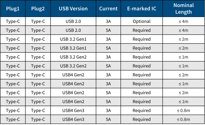
- For charging power levels of 240W, the charger, cable, and terminal equipment must all support EPR. In particular, cables must support up to 5A, 50V.
- 240W is the maximum charging power supported under Power Delivery.
- Three new fixed voltages have been added: 28V (above 100W), 36V (above 140W), and 48V (above 180W).
- Three sets of adjustable voltages have been added
The new USB PD architecture defines a more stringent power protocol to ensure that high-power products can be used safely while enabling greater maximum charging power. In addition, safety requirements for products with power ranges between 100-240W have also become more stringent. Do refer to your target region’s country legislation regarding safety regulations before sending products for import.
USB Power Delivery test instruments

PD Merged Test Specification:
- GRL C2-EPR
- Ellisys Explorer 350
- MQP-PDT
- LeCroy Voyager M310P
Type-C Functional Test:
- Ellisys Explorer 350
- LeCroy Voyager M310P
- GRL C2-EPR
Battery Charging 1.2 Compliance Test:
- MQP-PET
Source Power Test:
- QuadraMAX
Interoperability Test:
- Google Pixel 4 Phone
- Samsung Galaxy S21
- Google Pixelbook Go
- MacBook Air M1
- ASUS 4K Monitor
PD 3.0 Test:
- GRL C2-EPR
- Ellisys Explorer 350
- MQP-PDT
- LeCroy Voyager M310P
USB Embedded Host and Shared Power
USB Embedded Host allows USB peripherals to communicate directly with one another in the absence of an intermediary PC. Instead, Embedded Hosts enable direct connections between On-the-Go (OTG) devices, safely opening up communication channels with selected USB peripherals while simultaneously preserving battery life through power saving features. The continuous refinement of Embedded Host alongside USB Specifications has allowed electronic products to operate faster and more efficiently.
What is the difference between Host and Embedded Host?
There are subtle but significant differences between Host and Embedded Host that engineers should note. Additional features found within USB Embedded Hosts include support for specific peripheral devices or device classes, support for transfer types required by supported devices, and relaxed power requirements. Furthermore, hub support is also optional for embedded hosts.
An Embedded Host determines the types of devices that it can support through a Target Peripheral List (TPL). Entries in the TPL may include the VID or PID of specific products, or classes, subclasses, and protocols of products. Devices can perform dual roles when they support both Embedded Host and USB device functionality via two receptacles. For example, a phone functions as a peripheral device when downloading pictures to a PC, but becomes an Embedded Host when transferring pictures to a printer.
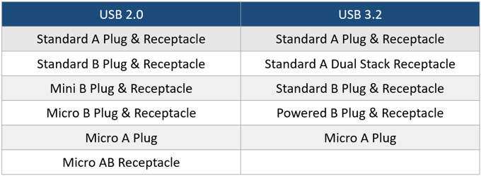
Determining the role that is being played boils down to the cables that are attached. When cables are attached to Type-A receptacles, the role of host is assumed. On the flipside, the role of device is assumed when cables are attached to Type-B receptacles. In most cases, both Type-A and Type-B receptacles must both operate concurrently unless they are only accessible one at a time. The advantage of USB OTG devices lies in their ability to dynamically switch between Embedded Host and peripheral device roles without changing cables. Instead of the typical Type-A and Type-B receptacles, OTG devices use a singular micro-AB receptacle that allows for adjustments by cable orientation.
Latest Shared Power Spec Updates
While Shared Power specifications are still in the developmental phase, OEMs who are looking to test this functionality within their products can already do so using the GRL-A1-EPR Analyzer. Assessing Shared Power functionality can allow manufacturers to gain first-movers advantage, as experts believe that automotive solutions surrounding this specification will rapidly surface over the next 3-5 years. Furthermore, testing speeds and capacities will only continue to increase. GRL’s test engineers are already setting the standard by integrating AI and AI-EPR into USB-IF PD interop and Shared Power interop suites, as well as testing power speeds of up to 240W.
EU Conformity to USB-IF Specifications (IEC 62680)
To comply with new EU requirements under the External Power Supply (EPS) Ecodesign Regulation and the Common Charger Directive, OEMs must demonstrate that their products meet USB Type-C® and USB Power Delivery (USB PD) interoperability requirements. Most product categories are subject to the requirements defined in the latest USB-IF specifications — specifically the USB Type-C® Cable and Connector Specification and the USB Power Delivery Specification — with the exception of laptop PC’s which will take effect in 2026.
The EU Conformity to USB-IF Specifications program was developed to address this regulatory need. It provides OEMs and ODMs with a clear pathway to generate documentation showing that their products conform to the USB-IF specifications referenced in EU legislation. Built on USB-IF’s established certification framework, the program leverages proven compliance processes to help manufacturers demonstrate technical alignment with EU requirements.
Where proprietary charging protocols are supported, participation in the program remains possible — provided the product satisfies the core interoperability criteria for USB-C and USB PD. For USB Type-C® cables and connectors (plugs and receptacles), the conformity requirements are identical to full USB-IF certification. In such cases, applicants should use the standard USB-IF certification and registration process.
USB-IF has also defined a minimal set of test requirements specific to this program, helping streamline product evaluation for EU conformity purposes.
Click here for details and FAQs on the USB-IF Specifications program.
Product registration & qualification by similarity
To participate in the program, manufacturers must have a USB Vendor ID (VID). Details on obtaining a VID and registering products are available on the USB-IF website. Once a product passes the required testing, USB-IF will issue an official notice of EU conformity.
For product families with shared designs or architectures, USB-IF offers a Qualification by Similarity process. This allows additional models to be added to the conformity list without repeated testing, provided no significant technical differences exist between variants.


