In-vehicle networks (IVN) form the backbone of modern automotive functions. They facilitate the flow of data required for advanced features such as advanced driver assistance systems (ADAS), infotainment systems, cameras, vehicle-to-vehicle communication systems, as well as remote sensing technologies that encompass radar for radio waves and LiDAR for light detection.
What is 10BASE-T1S?
Coordinating this many disparate automotive components is extremely challenging, much less ensuring that every single component meets compliance standards across various markets. 10BASE-T1S Automotive Ethernet networking technology aims to alleviate that challenge with twisted-pair cables specifically designed to transmit data at speeds of 10 Mbps through noisy and highly electromagnetic environments, such as automotives.
The name 10BASE-T1S is used to describe how this Ethernet technology facilitates data transmission over a single channel using baseband signaling for single-pair environments, unlike traditional Ethernet technologies that use four pairs of wires.
Of course, the introduction of 10BASE-T1S means that automotive manufacturers now have a new standard to adapt to after CAN/CAN-FD. Luckily, Technology Manager of Rohde and Schwarz Curtis Donahue, and GRL’s very own Global Automotive Director Rainer Eckelt have consolidated everything you need to know about 10BASE-T1S compliance in this article for your ease of reference.
Automotive ethernet and autonomous vehicles
The automotive space is becoming increasingly software-defined as cars become more autonomous and interconnected. Experts even predict that cars will achieve what is known as “Level 5 autonomy” by 2030, where passengers can fully rely upon automotive systems to monitor their surroundings instead of using their own eyes or hands.
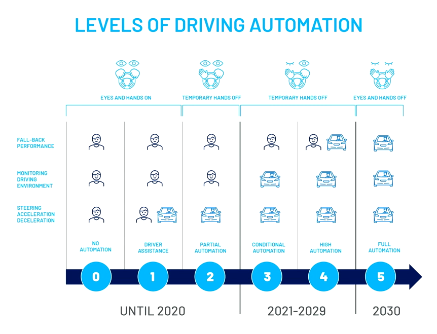
Levels of driving automation ranging from No Automation at Level 1 to Full Automation at Level 5.
Modern IVN architecture
Of course, achieving these system architectures will require manufacturers to design monitoring and fallback systems that are virtually foolproof. Impossible as it may sound, the automotive industry has come a long way from traditional vehicles to present day ACES-defined ones (Automated, Connected, Electric, and Shared). IVNs of modern vehicles already feature higher levels of computing power and data throughput required to secure and transfer data coming in from complex sensors. At the same time, the hardware of IVNs is also growing in sophistication, optimizing power consumption and weight efficiency.
One aspect of IVN architecture that has significantly improved is that of independent Electric Control Units (ECUs) that have gravitated towards domain centralized formats, where fewer domain controllers cover singular domains that are in turn composed of smaller censors and ECUs. Domain centralized designs have already helped cars achieve Level 3 autonomy, where drivers can sit back and observe as systems take over for steering, acceleration, and monitoring the surrounding environment.
Why 10BASE-T1S was created
The first proof-of-concept for 10BASE-T1S came in the early 2000s to 2010, where 100BASE-TX arrived alongside a slew of bus and switch accessories. 100BASE-TX was the first time manufacturers saw USB ports and infotainment systems incorporated into in-vehicle environments. Since then, automotive ethernet has taken over most networking aspects of in-vehicle systems, introducing both higher and lower bit rates for greater synergies within an increasingly complex automotive ecosystem.
The market potential of autonomous vehicles
With tech improvements come rising consumer awareness and demand. Today, more than half of automotive customers (64%) state that they’re willing to switch OEMs for better autonomous-driving capabilities. A similar proportion of US customers (66%) regard shared-mobility and keyless car entry as a base criteria. By 2030, it is projected that 95% of new vehicles sold will be interconnected, with electric vehicles sold in Europe occupying 53%.
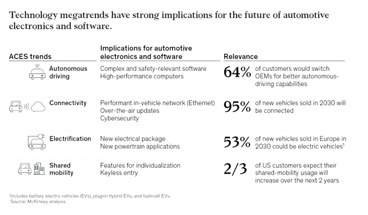
Source: McKinsey analysis
A technical overview of 10BASE-T1s
Ratified in 2019, 10BASE-T1S is one of the latest automotive specifications under the IEEE umbrella. While not necessarily the fastest specification, 10BASE-T1S helps manufacturers strike a balance between speed, cost, and systemic synergy.
While other automotive specifications use Pulse Amplitude Modification (PAM) signaling, 10BASE-T1S uses Differential Manchester Encoding (DME) to save complexity and cost. Additionally, 10BASE-T1S supports point to point and multidrop, allowing standard switch topology or single bus like known from CAN. The multidrop feature is applicable for channels that are up to 25 meters long and capable of supporting up to 8 nodes. Means, 10BASE-T1S includes a reconciliation sub-feature known as PLCA to facilitate the multidrop feature that is somewhat novel among IEEE automotive specifications.
PAM vs DME
One of the main advantages of 10BASE-T1S DME signaling is that it requires far lower cost compared to PAM. DME transitions between 0 and 1 levels occur far more frequently than PAM, contributing to quicker clock recovery and consequently lower cost products.
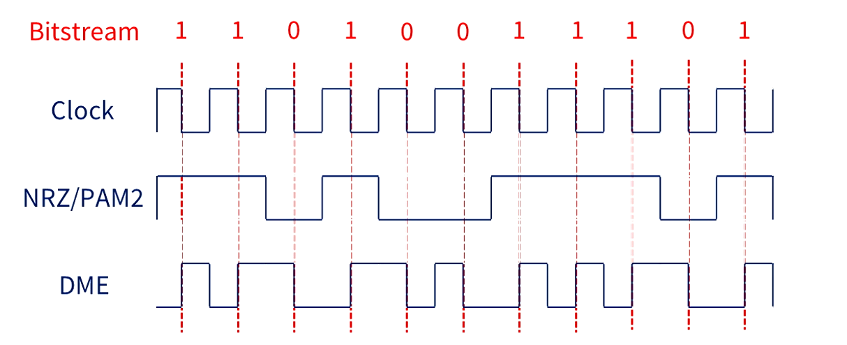
Sample bitstream demonstrating the frequency of transitions between 0 and 1 levels between DME and NRZ/PAM2.
Multidrop topology
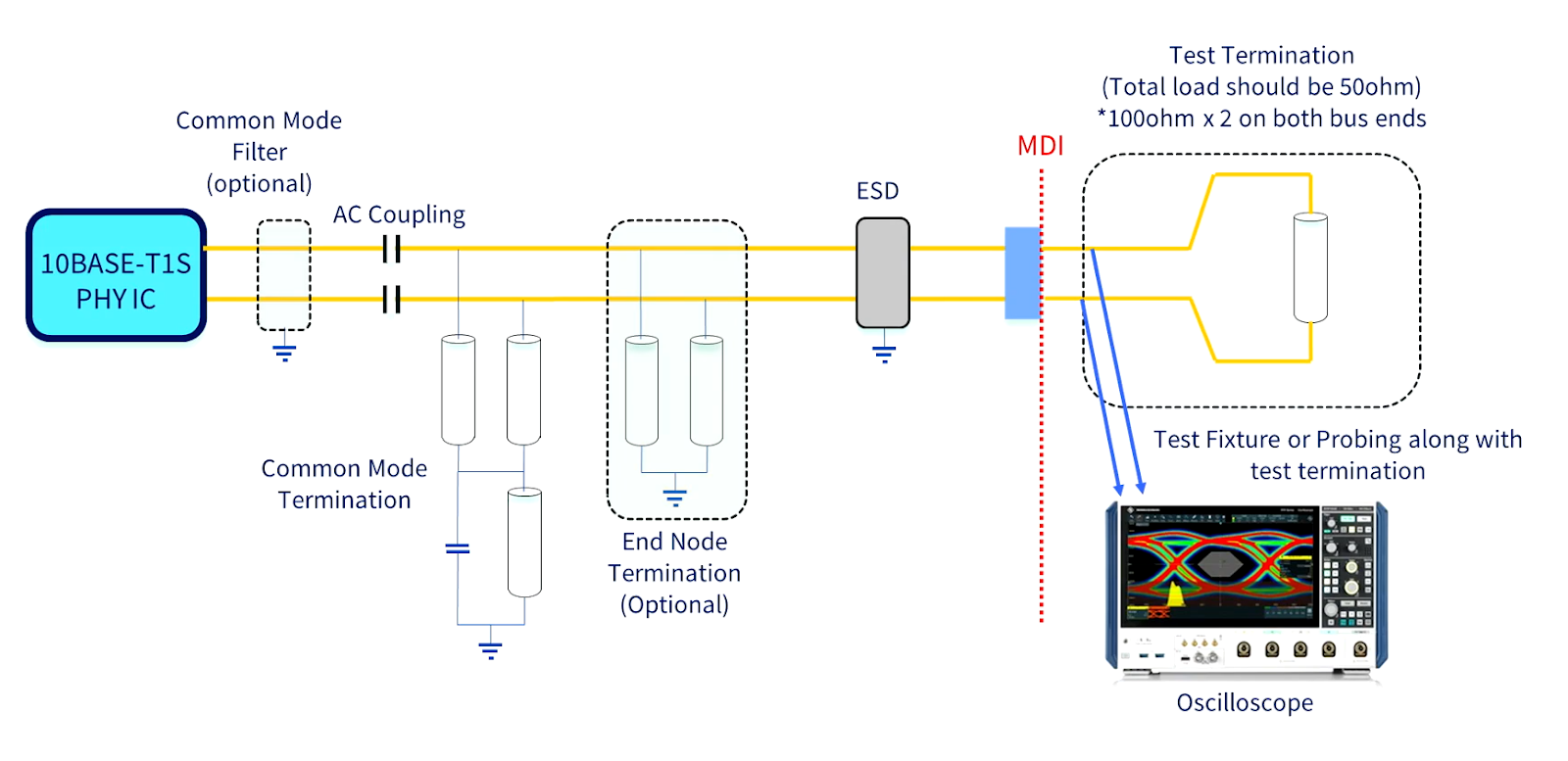
10BASE-T1S features a mixing segment that allows multiple devices to be connected to the same channel. Differential resistance between end node devices (100Ω) and drop nodes (50Ω) is what allows devices to communicate within very close timing and over the same channel.
An alternate setup could be a 100Ω terminal end node and single 100Ω impedance termination can be used instead of cabling to achieve the same effect.
Physical layer collision avoidance (PLCA)
Because traditional Ethernet is a largely point-to-point architecture that defines single MAC-PHY communication, the newer 10BASE-T1S also enables bus communication in multidrop mode while using the predefined MAC, where the reconciliation sublayer has to go between the PCS and the MAC. This allows each device to send a beacon, which is used to determine the order of device transmission and ultimately avoid collisions.
Applications and use cases for 10BASE T1-S
10BASE-T1S vs 100/1000BASE-T1 vs Legacy IVNs
10BASE-T1S is sometimes known as the goldilocks standard between 100/1000BASE-T1 and legacy IVNs. It supports multidrop architecture that facilitates data rates that are faster than older versions of legacy networks while keeping costs low. However, it must be noted that CAN-FD and CAN XL have also reached speeds of 8 Mbit and 20 Mbit respectively.
In comparison, preceding automotive technologies such as 100/1000BASE-T1 were high performance but also high cost, using PAM signaling with much higher bandwidth as well as switch-implemented sensors and activators. On the other hand, Legacy IVN such as CAN, CAN FD, and Flexray were low cost but also had lower data rates, while featuring the multidrop architecture which was later adopted into Ethernet. The main difference between CAN and its later Ethernet version is that the former used addr/prio for arbitration to BUS while the latter gained a defined “beacon” for precision timeslot.
Zonal architecture

Zonal architectures consist of zonal smart switches with high speed uplinks to System on a Chip (SoC) devices or high-speed switches connecting multiple SoCs. From there, there are point-to-point connections to 100/1000BASE-T1 high speed sensors and actuators as well as 10BASE-T1S for lower speed sensors and devices. In contrast to legacy sub-networks, all communication is based on Ethernet (TCP/IP, SOME/IP), which enables easier scaling of SDV.
10BASE-T1S compliance test specifications
To ensure conformance and stability, it’s important to figure out how to test 10BASE-T1S in the first place. This requires engineers to replicate multidrop technology within defined environments, in ways that are scalable and reproducible across multiple test stations.
PMA test specification
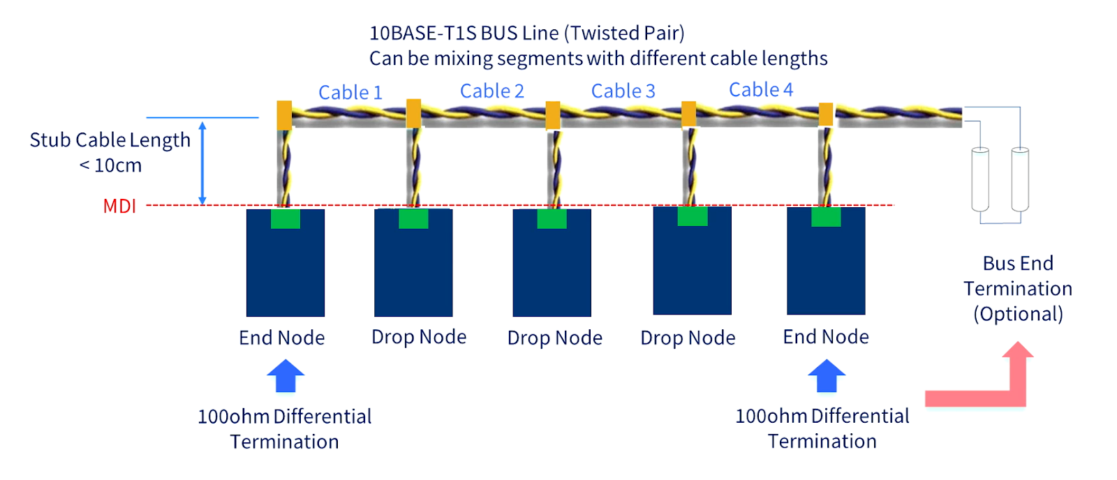
The following image depicts the setup of the BUS. Multidrop and BUS segments will create a lot of noise, which results in complexity in testing. Together with the TC 14 group, GRL has developed a ringing circuit board which confines the BUS device to a singular setup while still allowing for the recreation of the same environment on a real BUS.
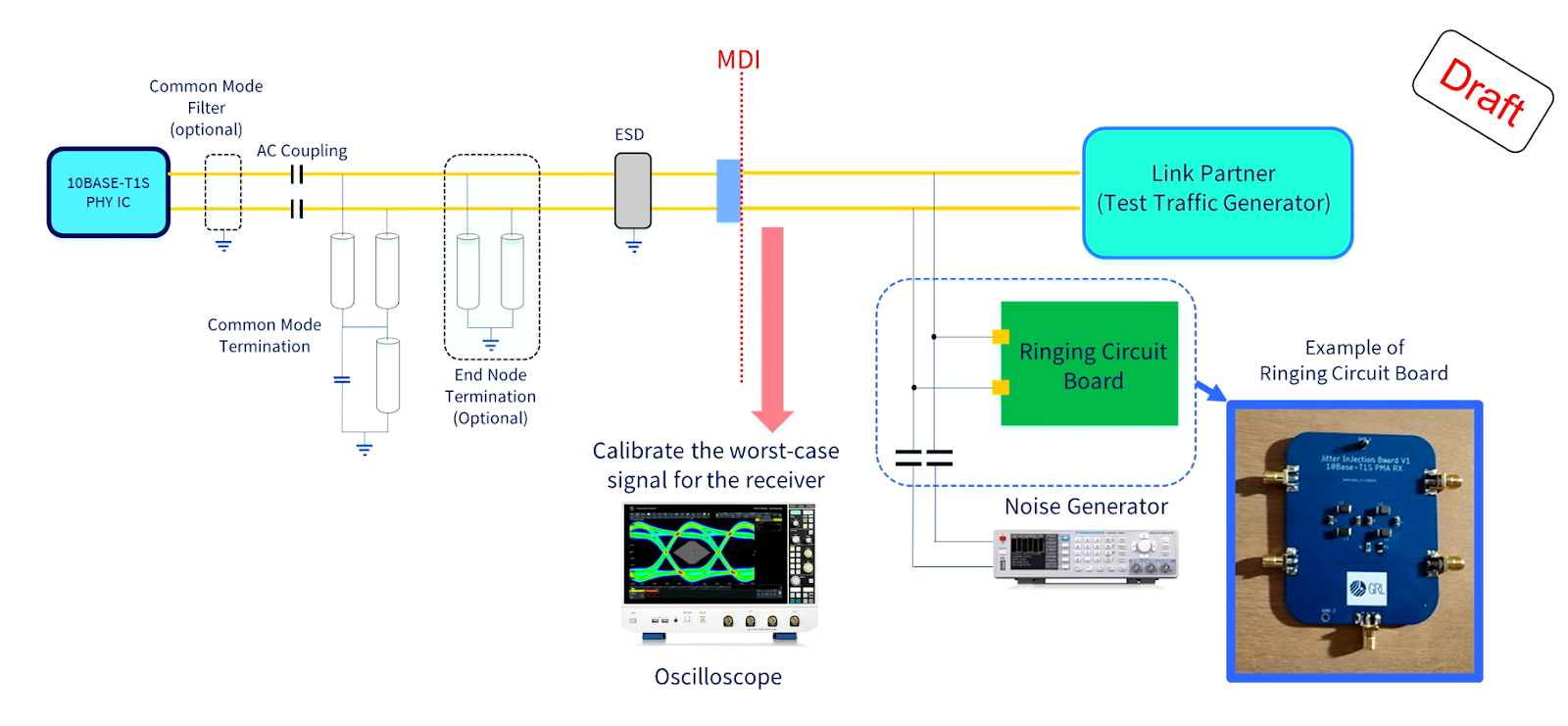
To go one step further and emulate real BUS scenarios, GRL has been working closely with the TC 14 team to figure out the most precise calibration setup and parameters on the oscilloscope. Full details can be seen in the webinar demonstration.
Watch the full webinar and 10BASE-T1S demonstration

PMA RX calibration
On the RX side where stress signals are emulated, the BUS setup, ringing board and frequency generator gives us the possibility of creating different levels of jitter. This will show us how the BUS will behave when the noise amplitude of a defined signal is increased.
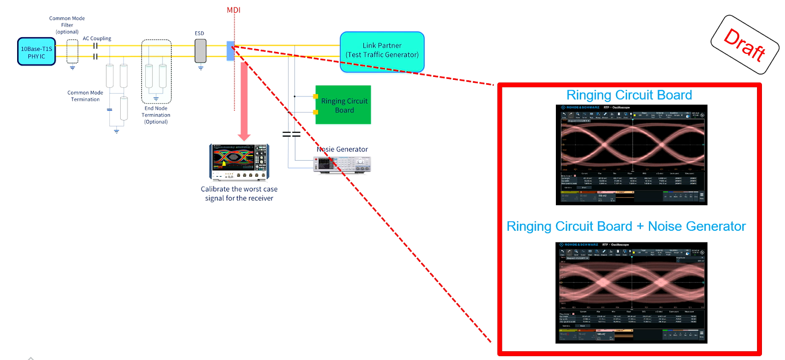
Typically, the link partner is used in test mode 3 and changing signal noise amplitude, shows us how the jitter is affected. Final values, flow of measurements and compliance validation are ongoing in OPEN Alliance TC14.
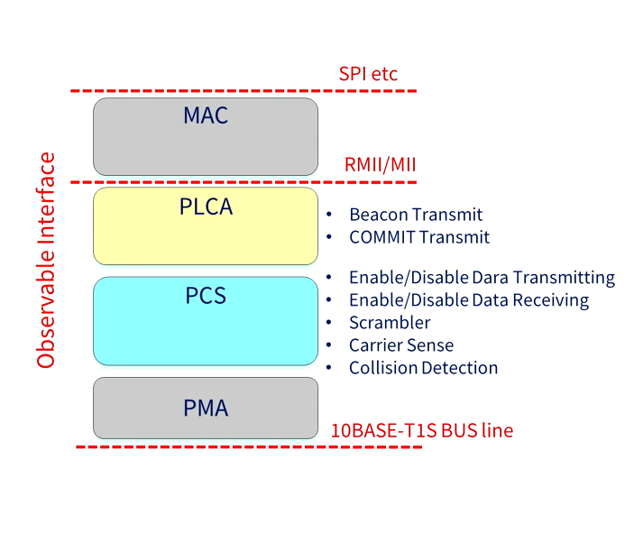
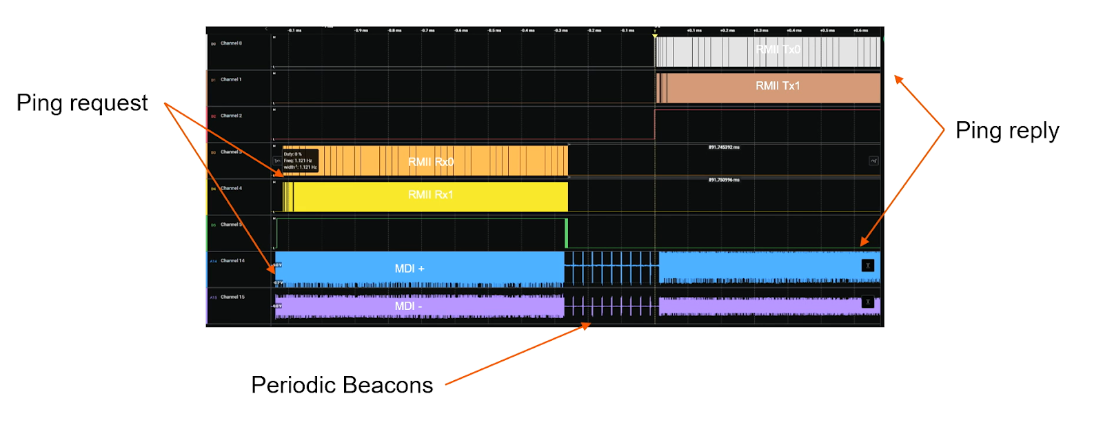
PCS/PLCA test specification
PCS/PLCA test specification deals with the middle part of the PHY, which influences encoding and transfer from the method phase from the SoC sending in some data from the digital side. As described above, 10BASE-T1S supports two layers, in comparison to 100/1000BASE-T1. On standard BASE-T1, where only the PCS layer encodes and transmits to the frontend, the PLCA layer enables a BUS interface on 10BASE-T1S which generates beacons for traffic-windows on each node for defined transfers.
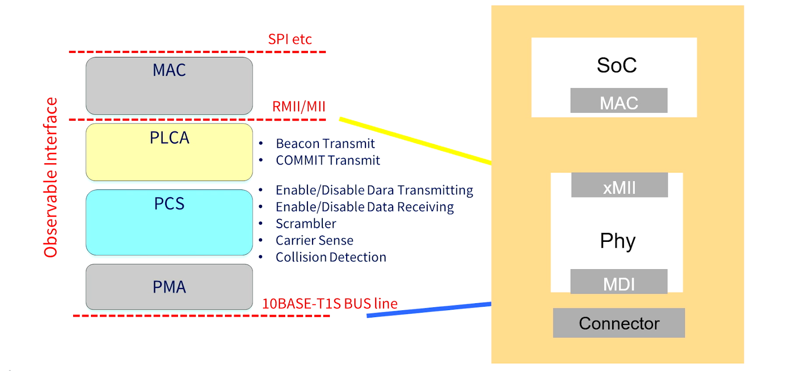
Taking the example of a ping request, the MDI represents where the data comes in on the physical side. This is followed by a short delay until the signal moves to the RMII interface on the other side.
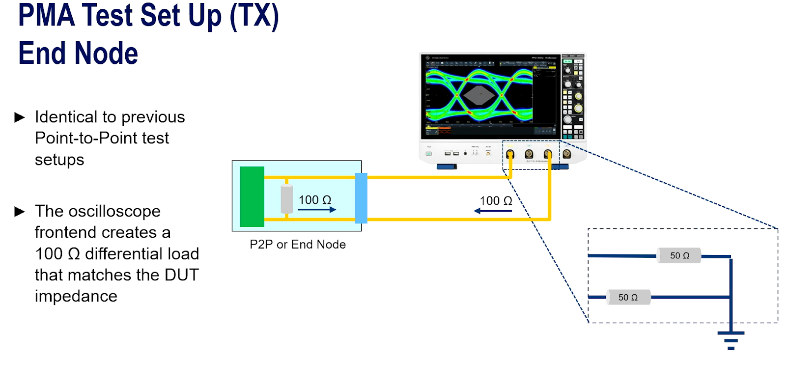
PMA test setup (TX)
In a multidrop segment, there are two end nodes with 100Ω impedance. In this scenario, one drop node is in transmit mode (50Ω) and the other is in receive mode (high impedance). When one is transmitting, the other is lying silent, effectively reducing signaling reflections.
This is identical to how it has been done for 100/1000BASE-T1 and other Ethernet technologies that facilitate point-to-point.
Replacing the point-to-point device with a drop node will create a mismatch between 50Ω and 100Ω in the test setup. This goes against the IEEE specification that requires PMA test cases to measure for both configurations.
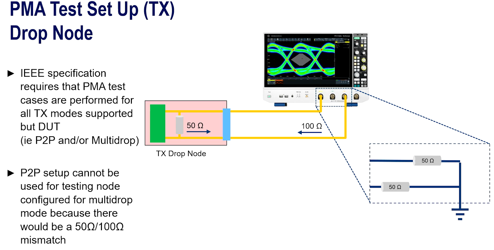
How then do we measure characteristics for 50Ω devices? In the multidrop example, the point-to-point end node and transmitting drop node creates a line termination of 100Ω on the opposite end of the link on the oscilloscope. That 100Ω is actually in parallel with the oscilloscope with the drop node or device under test.
This includes jitter and amplitude, which can be implemented in test fixturing, or adding optional hardware modifications to the PCB advice to the additional impedance.

Drive connected and compliant cars into new markets
GRL offers comprehensive automotive ethernet test services for 10/100/1000BASE-T1S, connecting you with IC vendors and Tier 1 suppliers necessary to an efficient certification process. Watch the rest of the 10BASE-T1S demo here, or schedule your own personalized demo with us.
About the author
Rainer Eckelt focuses on expanding GRL's testing services and solutions for high-speed interfaces like Automotive Ethernet, PCIe, SerDes and USB. He was previously working as Field Applications Engineer at NXP, the General Manager of FibreCode GmbH and Director of MOST Tool-Portfolio at SMSC/Microchip.
.png)
/%E6%B7%BA%E8%AB%87Ethernet%20%E5%B8%B6%E4%BD%A0%E5%85%A5%E9%96%80%E5%AD%B8%E7%BF%92%E4%B9%99%E5%A4%AA%E7%B6%B2%E8%B7%AF_featured%20image.jpeg)