Granite River Labs (GRL)
By Raymond Huang – Test Engineer, GRL (Taipei)
Ethernet is one of the most commonly-used technologies in local area networks (LANs) and the network architectures. It is based on the specifications established by the Institute of Electrical and Electronics Engineers (IEEE) and included in the IEEE 802.3 standard. This article is intended to provide an introduction to Ethernet (10M/100M/1000M) and the relevant tests based on the standard.
Ethernet is primarily designed to transmit information through multiple nodes on a network via cable, fiber channel and other media. Each Node has a specific address number. The global 48-bit MAC address (Media Access Control Address) is used to ensure identification among the Nodes and avoid transmission errors.
To understand Ethernet, it is helpful to be familiar with two technical terms:
- Network topology
- Carrier Sense Multiple Access with Collision Detection (CSMA/CD)
Network topology
Network topology can take a variety of forms, among which Star Topology and Bus Topology are the most common.
In Star Topology, a host controls the workstations around it and creates a star structure (as shown in Figure 1), with point-to-point on-line through media, such as Twisted Pair cable or Optical Fiber, which is convenient for routing and network maintenance. The quality and stability of the host are important.
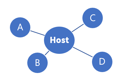
Figure 1: Star Topology
Bus Topology does not use a specific host as its core. Instead, this is shared by using twisted pair, coaxial cable and a Hub (see Figure 2). Routing is convenient and requires no specific settings when adding or removing a device. Its main disadvantage is that a problem occurring in any part of the transmission trunk will paralyze the whole network.
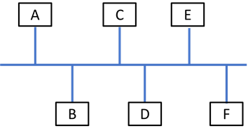
Figure 2: Bus Topology
CSMA/CD
CSMA/CD mainly operates in the bus structure. All the hosts (or workstations) that want to transmit data are required to broadcast data to the transmission media, while all workstations should be capable of receiving data broadcast on the network.
Ideally, only one source transmits information at a time. Before transmitting data, the host (or workstation) must confirm whether there is a signal being transmitted on the network. Data can be transmitted if no other signal source is transmitting, or if the rest of the workstations on the network are idle. Otherwise, the host must wait and keep detecting. If two hosts (or workstations) transmit signals at the same time, collisions between the signals will occur on the network (as shown in Figure 3), resulting in a message error that cannot be interpreted by the receiver.
When a collision occurs, the rest of units must stop transmitting signals. The transmitter sends out a jamming signal and informs the other workstations that a collision has occurred, and transmission of the signal should be stopped. The transmission terminal will wait for a Random Time before retransmitting.
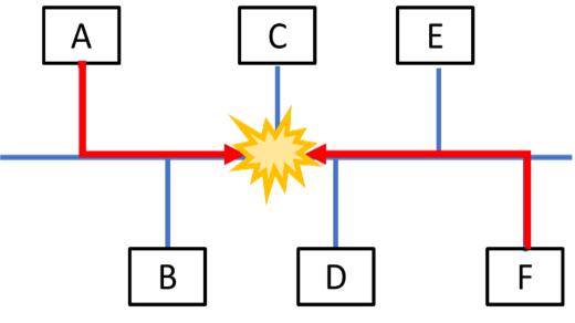
Figure 3
10Base-T:(IEEE 802.3 Clause 1 through Clause 20)
10 stands for 10 Mbps; Base, for Baseband; T, for Twisted Pair, and 10Base-T, for Cat-3 UTP.
10Base-T is Manchester Encoded. It defines 0 and 1 by the transmission state of the original signal. The minimum bandwidth required on twisted pair is 20M. It retains the original characteristics of CSMA/CD, but follows a tree topology (hybrid star and bus) in terms of network structure (See Figure 4).
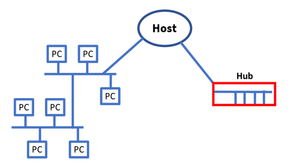
Figure 4: Common Hub
The device in the bus shown in Figure 4 is the common Hub. A disconnection between workstations and the Hub does not affect the transmission or reception of messages by the unit.
The Hub offers the advantages of both topologies in terms of routing and network maintenance.
The CSMA/CD properties of 10MBASE-T can be tested with the equivalent TPM (Twisted Pair Model). The quality of the signal is tested first. The test condition is when the Link Pulse and the signal of transmission returns to "Idle" after the transmitter and the receiver are connected. The impedance value of DUT should be confirmed to ensure that it matches the specification, because this could impact the return loss result (see detailed test items in Table 1).
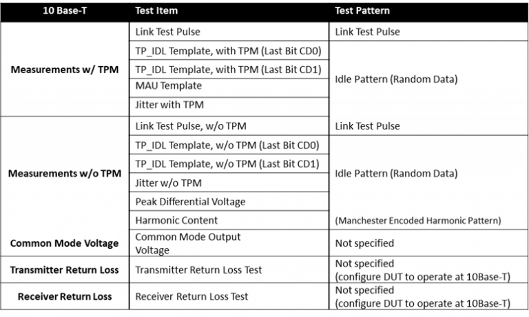 Table 1
100Base-TX:(IEEE 802.3 Clause 21 through Clause 33)
In 100Base-TX, data is transmitted at 100 Mbps, and X indicates that its Spec meets the X3T9.5 standard proposed by the American National Standards Institute (ANSI). 100BASE-TX uses two pairs of twisted pair cables – one for sending signals and the other for receiving signals. High bandwidth Cat-5 UTP is usually chosen to transmit high frequency signals and ensure signal quality,
The communication protocol is also CSMA/CD. It differs from 10Base-T in its encoding and Auto negotiation function. Unlike 100Base-TX, it adopts 4B/5B and NRZI (Non-Return Zero Inverted code) instead of Manchester Encoding. Then, it is encoded with Multi-Level Transmission-3 (MLT-3) and transmitted as shown in Figure 5. Therefore, the required bandwidth of the cable is 31.25 MHz (100 × 5/4 × 1/2 × 1/2 = 31.25 MHz). Major tests tend to focus on the signal integrity of MLT-3.
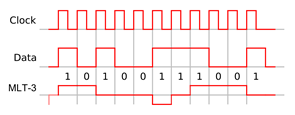
Figure 5
100Base-TX with Auto-negotiation is imported for downward compatibility with 10Base-T. It judges the capabilities supported by the receiver through Auto negotiation – such as transmission rate, the number of signal channels, transmission mode (full-duplex or half-duplex) – and then completes the transmission conditions after the transmitter is connected to the receiver.
Since the peak of Differential signal is significant to MLT-3 encoding, specifications have been formulated for the peak voltage (+Vout, -Vout) and Overshoot of both positive and negative voltages. Symmetry is also required for testing to avoid too large a gap between negative and positive voltages. In addition to voltage, the time offset is also specified, as shown in Figure 6. A large time offset will lead to signal distortion, resulting in a misjudgment of the signal as 0 or 1 by the receiver (see the detailed test items in Table 2).
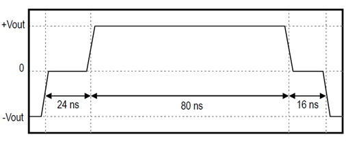
Figure 6
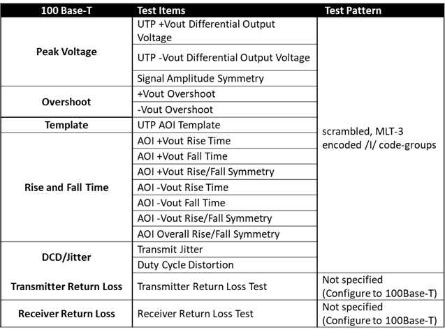 Table 2
1000Base-T:(IEEE 802.3z, IEEE 802.3ab)
The 1000Base-T Gigabit Ethernet (GBE) communication protocol also follows the CSMA/CD mode, with a Cat-5 UTP cable comprising four pairs of twisted pair wires used for signal transmission, and PAM-5(Pulse Amplitude Modulation 5) for encoding (see Figure 7).
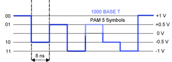
Figure 7
Four pairs of twisted pair wires can simultaneously transmit or receive signals, each at a frequency of 250 MHz. However, as two bits are expressed as one potential in PAM-5 encoding, the frequency of each pair may ultimately be measured as 125MHz. 1000Base-T is backward compatible with 100/10Base-T and has the same Auto negotiation function as 100Base-TX, so it can be downgraded to 100Base-TX if necessary. The Pam-5 code used by 1000Base-T also has Pulse-Shaping, which means that after the data is encoded, the five potentials are shown similarly to the continuous signals. This can reduce the high frequency noise and low frequency component, and ultimately strengthen the relative signal-to-noise ratio of the output.
The test items for 1000Base-T are shown in Table 3. Different test conditions have been defined for each item according to the specification:
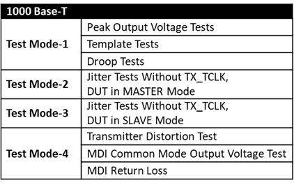
Table 3
Test Mode 1
Pattern Test Mode 1 is used to confirm the five accurate positions of PAM-5, to ensure that data transmission is error-free. It also confirms that the potential at points such as A, B, C and D does not shift too much, and that G relative to F, and J relative to H has not decayed too far. There is also a Template specification for this waveform to test signal waveform integrity to ensure signal quality.
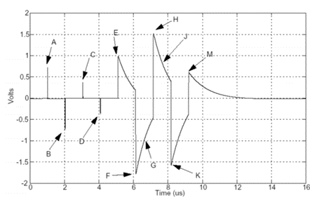
Figure 8
Test Mode 2 & 3:
Pattern Test Modes 2 & 3 are shown as periodic 125 MHz signals in Figure 9. These test modes confirm the amount of jitter in Auto negotiation through the Pattern in master and slave Mode to avoid Auto negotiation failure, by verifying whether the jitter of the signal complies with the specification.
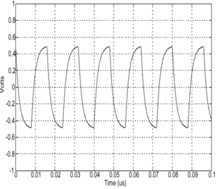
Figure 9
Test Mode 4
In Pattern Test Mode 4, the transmitter sends signals generated when passing through the scrambler generator polynomial. This is an 11-bit signal with iterative properties, as shown in Figure 10. A schematic of its iterative concept is shown in Figure 1. Bits followed by the 11th bit are output after performing an exclusive or logic operation (e.g. AND, OR, XOR). For detailed algebraic operations, please refer to IEEE 802.3ab.
Iterative test signals can be used to verify whether the level of electric potential distortion is within IEEE specifications and check whether the Common Mode caused by each Pair meets the specifications.
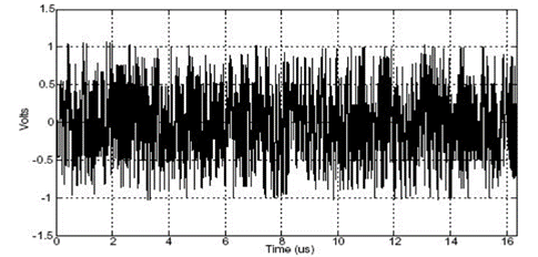
Figure 10
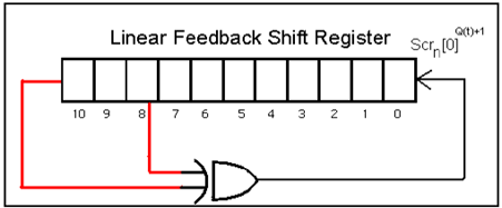
Figure 11
Granite River Labs (GRL) has found that with the increasing use of cloud computing by enterprises, the demand for servers has increased in recent years. Network interfaces are more widely used for a variety of reasons, and transmission speeds are improving, which also means that quality and testing requirements are increasingly important.

References
- IEEE Standard for Ethernet (IEEE Std 802.3™-2018)
- Keysight N5392A/N5392B Ethernet Compliance Test Application MOI
- https://linksprinterblog.wordpress.com/2014/05/14/there-is-more-to-life-than-increasing-its-speed/
- Wiki MLT-3 encoding
Author
Raymond Huang – Test Engineer, GRL (Taipei)
A graduate of National Taiwan University with a master’s degree in Chemical Engineering, Raymond Huang has over two years test experience and is familiar with the DisplayPort DisplayHDR and Ethernet test specifications.

.png)