By Sophie Lee – Senior Engineer, GRL
Display Stream Compression (DSC) is a type of visually lossless compression developed by the Video Electronics Standards Association (VESA) for ultra-high definition displays. It compresses image data to reduce the bandwidth demand on connections between video sources, such as Blu-ray players, PCs, games consoles, and displays, and outputs the content in high-resolution.
Offering low delay after compression, DSC supports a variety of video interfaces, including DisplayPort ™, HDMI® and MIPI. This document discusses the DSC test for DisplayPort (DP) certification.
Introduction
A complete DSC system requires an encoder and a decoder. The encoder is located at the DP transmitter (DP TX) end and compresses pictures before transmission. The decoder is fitted at the DP receiver (DP RX) end to decompress, restore and display the received picture data (see Figure 1). Both the DP TX end and the DP RX end must support DSC before the solution can be enabled.
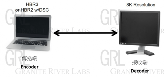
Figure 1
DSC uses predictive coding and establishes the index color history to compress image data. Predictive coding uses the DP TX end to predict the value of a target pixel and calculate an “error.” That error is then transmitted to the DP RX end as data.
The DP RX end follows the same predictive steps and adds the error, so the displayed pixel is as close to the original pixel as possible. This means that only the error needs to be transmitted, resulting in reduced data volume.
The Index Color History (ICH) stores the details of frequently occurring pixels. Upon transmission, only the index data – as opposed to the entire mass of data – are needed for compression purposes.
The compression flow at the DP TX end is illustrated in Figure 2, while Figure 3 explains decompression process at the DP RX end.
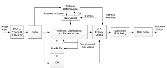
Figure 2: DP TX End DSC Compression Flow
From the VESA DSC specification (DSC v1.2a)

Figure 3: DP RX End DSC Decompression Flow
From the VESA DSC specification (DSC v1.2a)
There are three types of predictive coding: Median-Adaptive Prediction (MMAP), Block Prediction (BP), and Midpoint Prediction (MP).
Block Prediction resides at the DP RX end. When the DisplayPort carries out Link Training, it will notify the DP TX end through the DisplayPort Configuration Data ("DPCD").
The DP TX end does not notify the DP RX end of the predictive coding or ICH methods it is using for compression. Instead, it uses the common mechanism to determine based on the picture’s pixel composition. First, it determines whether to use predictive coding or ICH. If predictive coding is selected, the DP TX end will first choose to use MMAP or BP, and then decide whether to use MP. When predictive coding is used, the minimum error after the coding should also be selected.
To accelerate the coding process and reduce compression distortion, the DSC technology utilizes Slice, which cuts up every picture frame and simultaneously encodes the cut slices. The DSC can support 1, 2, 4, 8 and even more slices. However, it should be noted that the unit is slice/line, and the line refers to the pixel that adopts the raster-scan sequence as a line during the picture forming process.
In addition to different numbers of slices, DSC may also use slices of different lengths and widths. In Figure 4, all the images have 4 slices/line. However, the picture in the upper right corner is cut into the strip slices, while the picture in the lower right corner is cut into wider rectangular slices. The length and width of slices used are subject to the number of slices supported by the DP TX end and DP RX end, and the DSC compression or decompression rate. When the Link Training is conducted, the DP TX end and the DP RX end will communicate and run the DSC in a mutually supported combination.
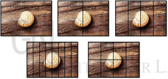
Figure 4
The DSC should start when the DP TX end is connected to the DP RX end and Link Training is conducted. Figure 5 shows the process of enabling Link Training on DSC. The DP TX end reads the Extended Display Identification Data (EDID) of the DP RX end, and then the DisplayPort Configuration Data (DPCD), and checks the capacity of DP RX end and whether it supports DSC. If it does support DSC, the DPCD will be written in before the end of Link Training to enable DSC functions (Please refer to Table 1 for the DSC-related DPCD address).
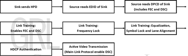
Figure 5
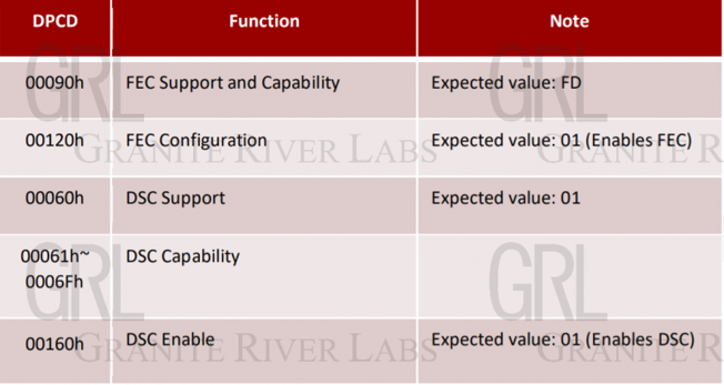
Table 1
When the Link Training is complete, and the picture data are transmitted, further communication of DSC-related capacity through the Main-Link Protocol is required.
The Main-Link Protocol consists of several parts: Control VB-ID, Metadata, Audio, Picture Parameter Set and End of Chunk. Among them, the Control VB-ID, Picture Parameter Set and End of Chunk include the DSC-related information, which is transmitted from the DP TX end to the DP RX end together with the picture data.
When the 160h address is written during the Link Training process, the DP TX end will write the requirements for enabling DSC functions in VB-ID (Compressed Stream Flag) and write the relevant DSC function information in the Picture Parameter Set. According to the VESA specification, the VB-ID in which the enabling and disabling of DSC functions is included, must be located at the line before the picture information (see Figure 6). Then, the DP TX end writes the information related to DSC functions in the Picture Parameter Set, including the DSC version, picture length & width, color format used by the picture, and color depth. The information that should be noted in the DP DSC test is listed in Table 2.
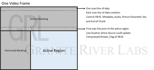
Figure 6
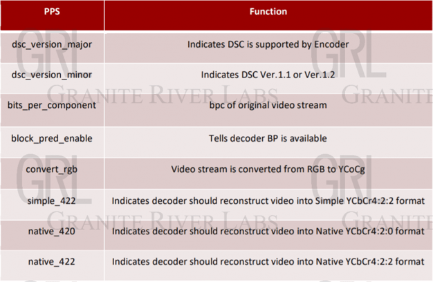
Table 2
The DSC Test in DP Certification
Since the DSC adds the DSC-related information in the DPCD and Main-Link Protocol, one of purposes of the DSC test is to check the Link Training and Main Link Protocol processes. The DSC involves many different factors, including resolution, slice, color format, color depth, encoding and decoding methods. Therefore, the test is conducted with regard to different combinations. Furthermore, since the DSC boasts no visual distortion, a naked-eye check on whether the picture is normal in the test link is required. The following table (Table 3) lists (in order) the items to be tested at the DP TX end.
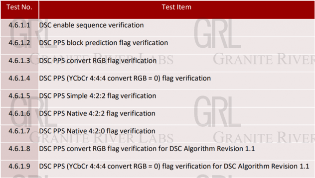
Table (3)
The first two test items in the table only check whether the DSC is correctly enabled under normal conditions and when the BP is used. With the exception of Link Training & Main-Link Protocol, all other items require pictures to be checked by naked eye.
The last two test items, 4.6.1.8 & 4.6.1.9, require checking of the downward compatibility of the product, to ensure that the DSC is also successfully enabled in a scenario where the DP RX end only supports the DSC 1.1. The method for testing the DP RX end is similar, but more involved. There are a total of 26 test items, including color format and color depth, Block Prediction, compression rate, number of slices and number of channels in a color format.
As resolution has grown from 2K, to 8K and transmission rates increase, DP is evolving and new versions are rolling out. However, although both the DP TX end and DP RX end can support such high resolution and transmission rates, the connecting cables may encounter hardware limits and be unable to resolve the problem of signal loss at high transmission speeds. Therefore, the introduction of DSC into the DP interface will allow fine resolution even at lower transfer rates.
Consumer demand for higher resolution content will only continue to grow. Until the hardware barriers are overcome, DSC will remain worthy of further study.
References
- VESA Display Stream Compression (DSC) Standard Version 1.2a – 18 January, 2017
- VESA DisplayPort (DP) Standard Version 1.4a – 19 April, 2018
VESA® DisplayPort® DSC Link Layer Compliance Test - Specification Version 1.4a Revision 1.1 Draft 6 – 18 November, 2019
Author
Sophie Lee – Senior Engineer, GRL
A graduate of the Department of Mechanical Engineering at National Taiwan University, Sophie Lee has more than three years of test experience and is familiar with DisplayPort, Ethernet and other test specifications.

Specifications and descriptions in this document can be subjected to changes by GRL without prior notice.
Release date: 2021/04/29 AN-210429-TW

.png)
/DisplayPort%E2%84%A2%202.0%20Overview_featured%20image.jpeg)
/adaptive%20sync.png)