Think you know USB 3.2 compliance test requirements well enough already? Take the quiz to find out how truly well-versed you are in electrical compliance testing!
Why is USB 3.2 compliance so challenging?
The (Universal Serial Bus) USB Type C connector is a cable that is as ubiquitous as its name suggests, so much so that even the latest generation iPhones — which had been charged by an exclusive Lightning cable up until today — featured it after 14 generations. But for all the convenience that USB cables bring, there are a surprising number of challenges that manufacturers have to grapple with when designing USB cables and compatible products.
To detangle these testing complexities to our global audience, our very own EMEA Laboratory Director Pascal Berten met up with Senior Application Engineer for Oscilloscopes, Johannes Ganzert, at the Rohde & Schwarz’s Munich office on October 4 2023. The conversation on debugging USB 3.2 transmitters (Tx) and receivers (Rx), as well as USB interface debugging demos through Rohde & Schwarz’s proprietary oscilloscope was broadcasted to hundreds of live viewers.
USB 3.2 introduces a whole host of test challenges. While its multi-lane operational specification is designed to accommodate higher levels of bandwidth demanded by new generations of PCs, consumer electronics, display, and mobile architectures, this also generates crosstalk issues within USB systems as unprecedented levels of data are transferred across the two lanes of 10Gbps.
In previous USB iterations, testing either the transmitting or receiving end would have sufficed. However, USB 3.2 specification testing requires manufacturers to capture all four lanes of data to get the full picture of crosstalk impact. To accomplish this, dual lanes on a BERT need to send out signals simultaneously. Balancing performance across all four pairs of signals is the only way for manufacturers to accurately capture how their device will perform under real world conditions where multiple variables are involved.
View the recording of the Technical Webinar: USB 3.2 Electrical Compliance Test.
What’s the difference between USB 3.0 and 3.2?
USB 3.0 was released in 2008, over a decade earlier than USB 3.2 which was only recently made public in 2022. Today, the generic term ‘USB compliance’ no longer refers to the previous 3.0 standard, but the new 3.2 specification.
Many updates were implemented between these two versions. Notably, the update from Gen 1 to Gen 2 doubled data transfer speeds from 5Gb/s to 10Gb/s. Additionally, many electromagnetic compatibility (EMC) improvements were made, especially to the connector portion. Perhaps most significantly, Type-C further increased data transfer speeds from 10Gb/s to 20Gb/s.
What’s the difference between USB 2.0 and 3.0?
Dating back to 2000, USB 2.0 operates at a transfer rate of around 480 Mb/s compared to USB 3.0’s 5Gb/s. USB 3.0’s data transfer capability was invaluable for its time, as it made hefty data backups or large-scale transfers involving external hard drives possible. The upgrade from USB 2.0 to 3.0 also saw the number of connector wires increase from four to nine, significantly enhancing speed, bandwidth, and power output.
Full backwards compatibility of USB 3.0 ports meant that they could seamlessly work with other USB versions, including 2.0. This meant that USB 2.0 drives could be plugged into 3.0 ports, although it did limit drive operation speeds to those of USB 2.0. Design wise, USB 2.0 ports had a black interior, while USB 3.0 ports were coloured blue.
Get a full overview of USB specification updates by downloading the Technical Webinar deck.
Do USB 3.2 Gen 2 products need to be compliant with USB Gen 1?
All Gen 2 (Super Speed plus) products must be compliant with Gen 1 (Super Speed). Similarly, all USB 4 products are also required to undergo USB 3.2 electrical testing.
To be clear, achieving compliance with USB-IF requires more than just electrical compliance. Manufacturers must attend a workshop or conduct testing at Authorized Test Labs (ATLs) such as GRL to become officially certified.
Preparing for USB 3.2 compliance testing according to USB-IF requirements
Test equipment requirements
High-performance oscilloscopes (e.g. RTP164) are required to accurately perform USB-IF compliance testing. The process can be smoothened with USB automation software.
Additionally, a high-performance Bit Error Rate Tester (BERT) that is capable of pattern generator and can force the product back into a USB loopback is also required for receiver testing.
Finally, it's important to ensure that the SMA cables used in the test process match.
Setup requirements
Fixtures required to execute testing used to be sold by USB-IF, but have since been discontinued. Instead, manufacturers must obtain Gen 1 Legacy Connectors from Fixture Solution and Gen 1/2 Type-C Connector from Wilder Technologies. Fixture solution will also provide Gen 2 Legacy Connectors by the end of 2023. Proper cables will also be offered by these providers.
Want a faster way to comply with USB standards? Check out our USB compliance services!
USB 3.2 Gen 1/2 setup configurations for Tx and Rx
The USB-IF compliant specification is derived from the USB 3.2 specification and Engineering Change Notice (ECN). This specification details how Tx and Rx measurements and other electrical parameters need to be executed.
Some actually consider USB 3.2 compliance tests to be easier thanks to new compliance test modes. Test modes CP0 to CP8 are defined for Gen 1, while CP9 to CP16 are defined for Gen 2.
The lowest numbered test mode will be activated from the moment a device is connected to the tester, and toggled up incrementally once a Ping.LFPS is sent out.
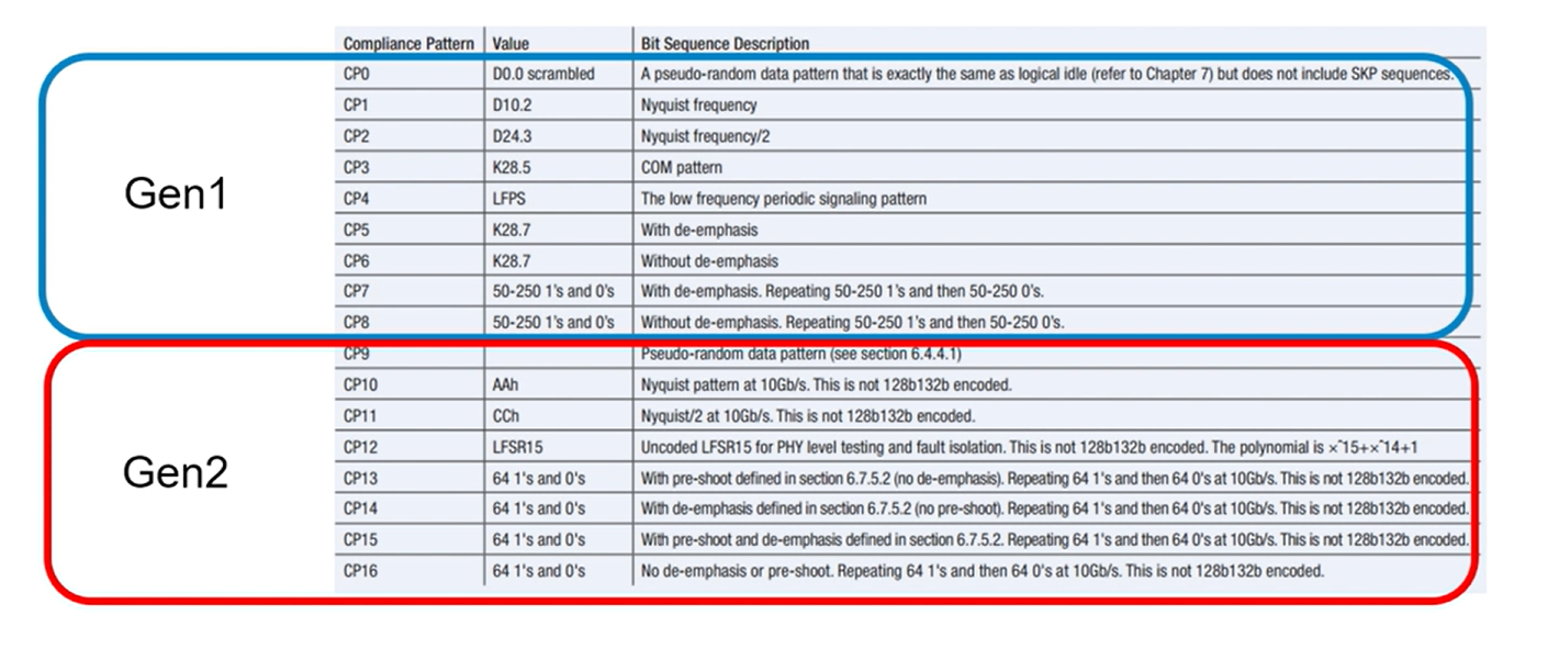
Test modes CP0 to CP8 are defined for Gen 1, while CP9 to CP16 are defined for Gen2.
USB 3.2 Gen 1/2 upstream setup Tx
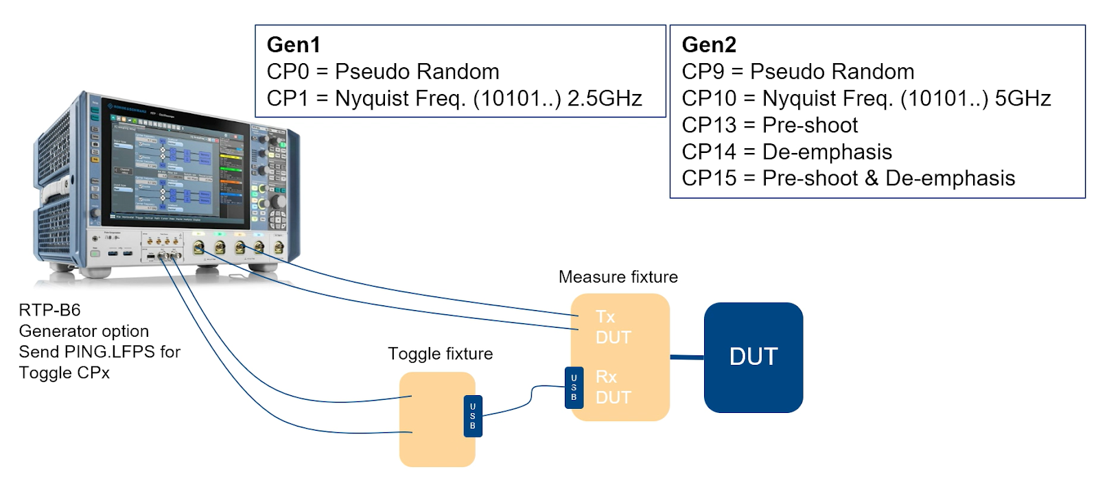
USB 3.2 Gen 1/2 upstream setup Tx.
Upstream ports are devices or hub ports that can also be connected to the PC side. A typical USB 3.2 Gen 1/2 upstream Tx test setup consists of a measure fixture (AKA scope) and a toggle fixture. The latter will be used to send a ping.LFPS.ping to the DUT so that the system may toggle to the next test pattern. Toggle fixtures don’t have to fulfill specific requirements as long as DUTs can receive their pings. It is, however, important to use the appropriate measure fixtures.
Obtain the full list of USB 3.2 Gen 1 upstream long channel Tx measure fixtures.
USB 3.2 Gen 1/2 downstream setup Tx
Devices are connected to downstream ports, which can only be A ports or C ports. For the most part, setup for USB 3.2 Gen 1/2 Tx testing is exactly the same as the upstream setup. The only difference is the additional xHCI HSETT tool connected to the DUT, which forces the downstream port in Tx-Compliance_Mode and allows for toggling between CPx. HSETT is a free tool that can be obtained from the official USB-IF website.
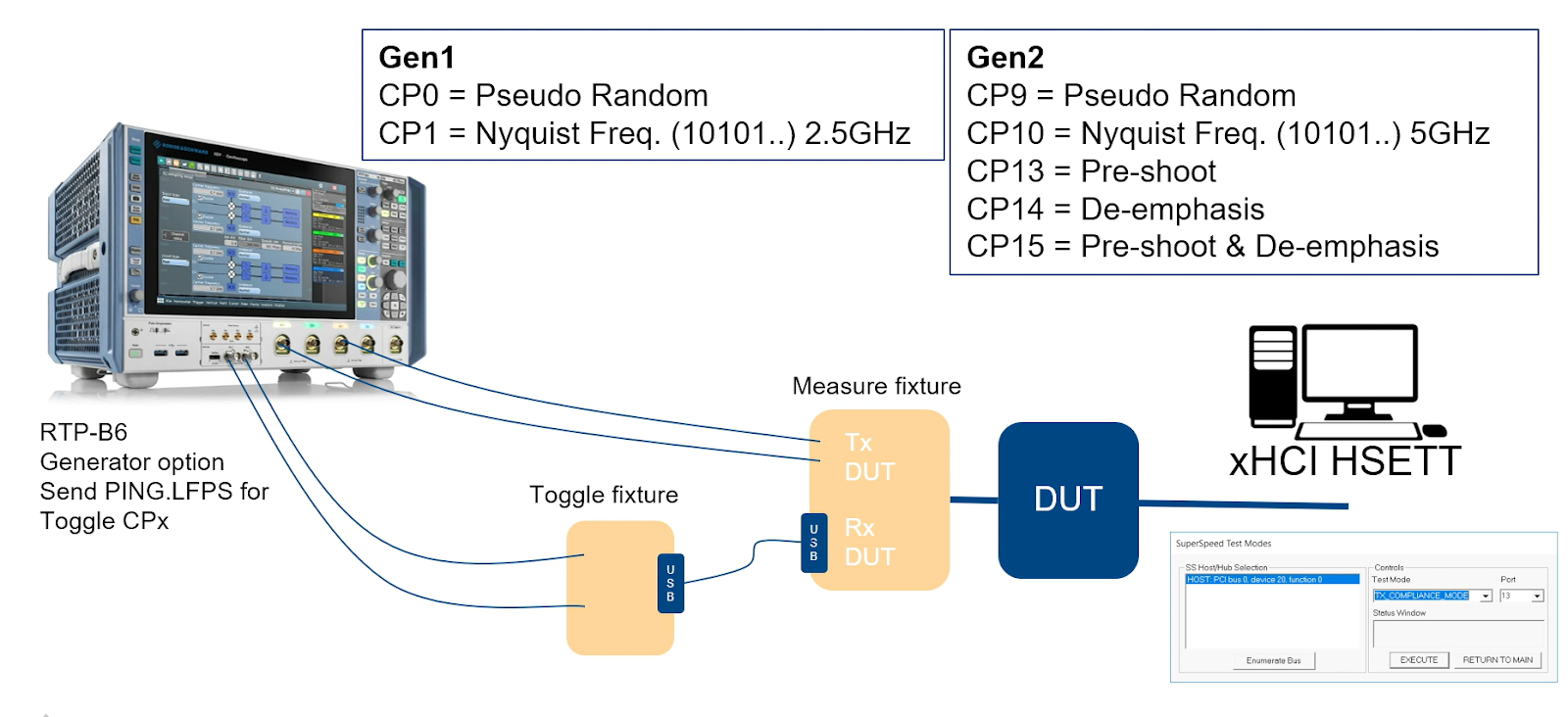
USB 3.2 Gen 1/2 downstream setup Tx
Before connecting the fixtures, it's important to set the downstream port to test mode. Doing so may require additional steps if your host OS is not Windows. While most Hosts in today’s market do support test mode, it’s not uncommon for manufacturers to encounter roadblocks in this phase of testing.
Reach out for personalised USB testing advice and assistance.
USB 3.2 electrical compliance criteria
Low frequency periodic signaling parameters
If the test system has been set up properly, the connected device will immediately send a Polling.LFPS once it is powered on. With modern test automation software, these results can be obtained instantly to determine whether a device passes or fails compliance test parameters.
Devices that are compliant with USB 3.2 specifications should fulfill the following USB 3.2 low frequency periodic signaling parameters:
- Vpp >=800mV <= 1.2V
- tPeriod >= 20ns <= 100ns
- tBurst >= 600ns <= 1.4 µs
- tRepeat >= 6µs <= 14 µs
- Rise/Fall time <= 4ns
- Duty cycle >= 40% <= 60%
- AC Common Mode Voltage <= 100mV
Spread spectrum clocking
Spread spectrum clocking is another mandatory measurement under USB compliance. Manufacturers may obtain a measurement by going to a CP1, although it is important to select the right vendors as some do disable spread spectrum clocking despite it being a compulsory test requirement.
Gen 1 Eye diagram and jitter measurement
As with all other test modes, toggling is done by sending a Ping.LFPS on the Rx Pair. Once you’ve arrived at the eye diagram and jitter test mode, measurement can be done with CP0 and CP1. Note that this test is usually done towards the end of the compliance procedure. The results expected for compliant devices are as follows:
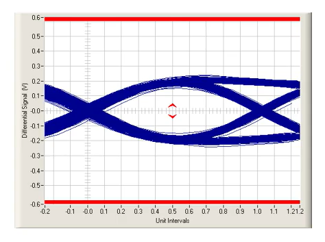
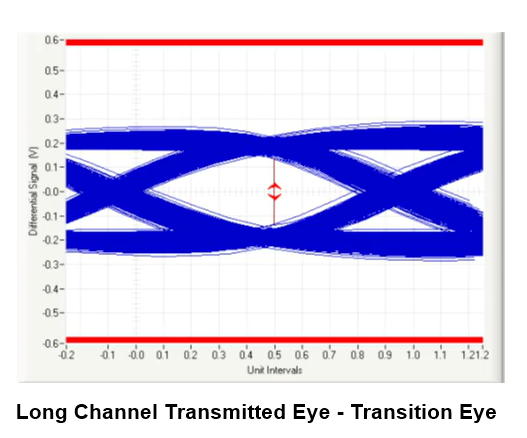
Long Channel Transmitted Eye: Transition Eye
If the eye diagram generated features top and bottom layers that do not touch, the device will be deemed to have passed the compliance test.
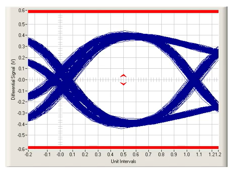
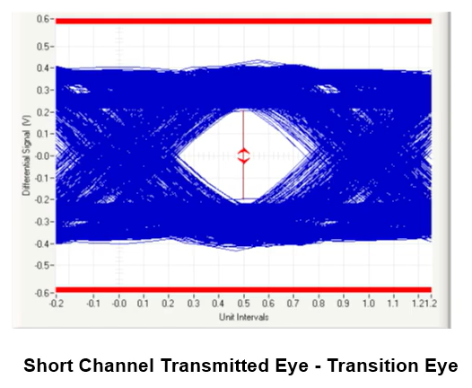
Short Channel Transmitted Eye: Transition Eye
Short channel eye diagrams typically have a wider eye compared to that of long channels.
Passing requirements of Gen 1 Jitter and Eye are as follows:
- CTLE done in the making of the EYE diagram
- Tj at BER-12 <= 132 ps with CP0 at TP1
- Dj <= 86 ps with CP- at TP1
- Rj <= 3.27 ps with CP1 at TP1 (these days, Rj is no longer a passing requirement, but simply an informative metric)
For long channel measurements, an appropriate S-Parameter is to be provided by the USB-IF through the RTP scope. Additionally, long channel losses will also be dependent on the type of USB connector and up or downstream port used.
Gen 2 Eye diagram and jitter measurement
Eye diagram and jitter measurement for Gen 2 is actually very similar to Ge1, with the test patterns CP9 and CP10 deployed instead. Toggling between test modes is done by sending Ping.LFPS on the Rx pair.
GRL Pro Tip: Be sure to look at the margins of each measurement for a clearer picture of the appropriate eye width and eye height.
Passing requirements of Gen 2 Jitter and Eye are as follows:
- Unlike Gen 1, Gen 2 requires both CTLE and DFE equalization to be done during the making of the EYE diagram.
- Tj at BER-12 <= 67.1 ps with CP0 at TP1
- Dj <= 53 ps with CP0 at TP1
- Rj <= 1 ps with CP1 at TP1 (as with Gen 1, Rj is no longer a passing requirement, but simply an informative metric)
Note that long channel measurements are the same as short channel end setup measurements. The only difference is that the RTP scope embeds the USB-IF S-Parameter to the signal. And aside from devices with captive or tethered cables, the same S-parameter is always used for Gen 1 long channels.
Pre-shoot and de-emphasis* (Gen 2 only)
USB Gen 2 compliance has one additional test criteria in the pre-shoot and de-emphasis. This is only applicable for Gen 2 and requires test patterns CP13, CP14, and CP15 to execute. It can be difficult to diagnose the outcome of the test just by looking at it. Instead, it is recommended for manufacturers to toggle between test patterns and observe how the differential voltages change.

USB Gen 2 pre-shoot and de-emphasis graph.
Mandatory USB 3.2 transmitter tests
The USB 3.2 transmitter automation solution has an RTP Generator for toggling between CPx. The RTP will also guide users through setup and test patterns, and produce a report at the end.
It’s important to test the receiver in both orientations for type C, and to test both modes when the product is a DRD (Host & Device). For USB 3.2 Gen 1/2X2, testing all data lanes is necessary. Finally, remember to use proper USB fixtures, cables, and SMA cables.
Mandatory USB 3.2 receiver testing
USB 3.2 receiver testing is done with the short channel and behind the long channel. The long channel is dependent on the speed and type of connector, while the Pattern Generator (PG) will send the calibrated compliance test pattern to Rx of the product under test. This will include:
- Maximum level of allowed Jitter
- Rj & Dj (Sj)
- SSC (33KHz Downspread 5000ppm)
- Minimum voltage
To begin, place the product under test in loopback (this can be done by the PG). The BERT will read out error send back by product under test at Tx. According to the USB 3.2 specification, BERT should sit between 10 to 12. If the DUT is Type-C, all testing is to be repeated with the alternate Rx path.
USB 3.2 Rx testing
Calibration
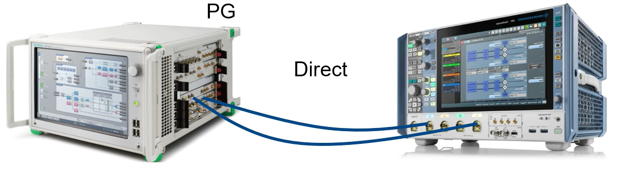
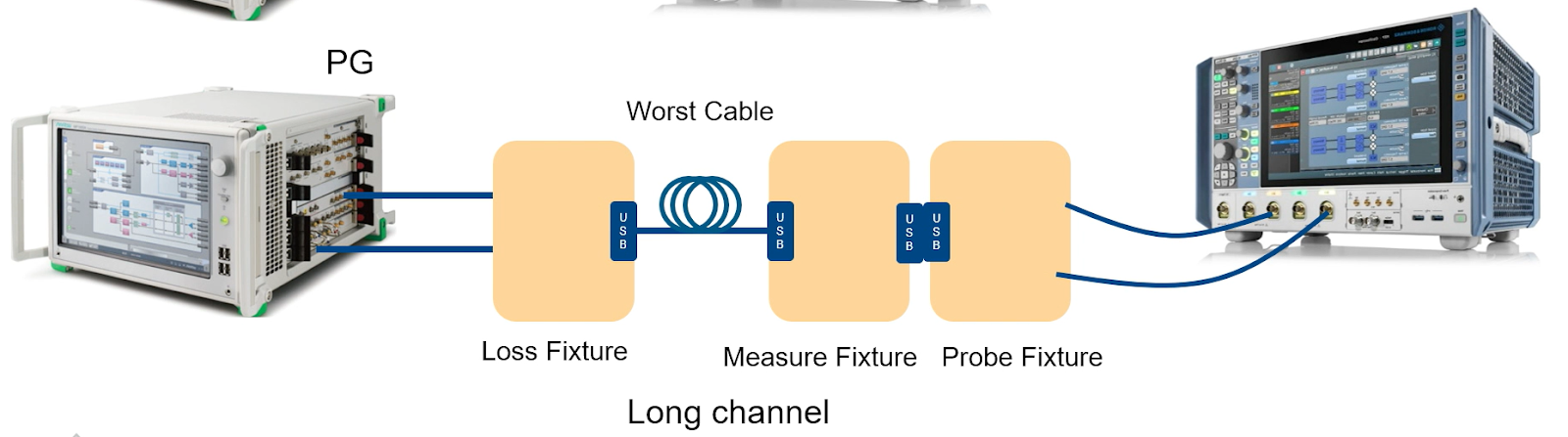
USB 3.2 Rx calibration setup.
Before conducting USB 3.2 receiver testing, it is essential to calibrate the pattern sent to the DUT. This needs to be done for both long and short channels, with the following parameters being calibrated:
- Voltage swing and de-emphasis (for short and long channel)
- Rj, Sj and Tj
Calculations are done in the background with SigTest, which is a long process where automation is highly recommended. Even when automated, calibration has a lead time of four hours. Taking the manual route will take up several days and often result in a significant number of errors since many calibration values need to be tracked. Do note that setups need to be calibrated again whenever USB or SMA cables are changed.
Testing
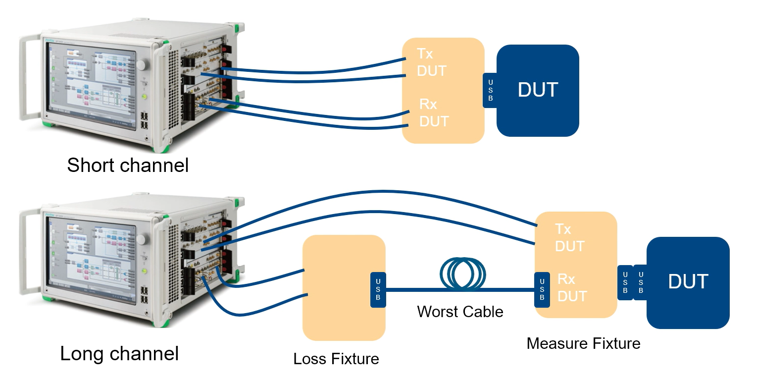
Setup for USB 3.2 Rx Testing.
Once calibration is complete, values stored within the BERT will be used for testing. Compliance testing will be conducted at the maximum allowed Sj.
As with calibration, automating the test process is highly recommended. The automated solution will place the product under test in the required loopback mode, a procedure that is extremely challenging to perform manually, taking up to several business days with significant room for error.
While not officially required for compliance, it is strongly advised for testers to conduct receiver tolerance tests to identify the amplitude and jitter margin of the product. Calibration will take around four hours, so be sure to use the proper USB fixtures, cables, and SMA cables from the outset to avoid do-overs.
Remember to test both modes when the product is in DRD (Host & Device), and all data lanes for USB 3.2 Gen 1/2x2.
Common issues encountered during USB3.2 receiver testing
Failure to enter loopback
Whenever a product fails to enter loopback, testers should first verify the setup with a reference product. If the setup is confirmed to be correct, further troubleshooting can be conducted by disabling the jitter or increasing the amplitude during the loopback training.
It’s not uncommon for Type-C cables to not enter loopback because the incorrect lane was selected. Flipping the cable or making the proper setting on CC line with the jumper of the tester fixture often remedies this.
Failure in receiver tolerance tests
When a product fails receiver tolerance tests, the PHY’s Equalizer settings may be adjusted on Re-Timers or Re-Drivers during implementation. Do note that High amplitude on Tx may result in crosstalk on the Rx path, which will cause the Rx test to fail.
Bad PCB design
Bad PCB designs can result in test failures. Often, this stems from traces being too long or not matched. It’s important for manufacturers to abide by PCB design rules to prevent this from happening.
Get the full list of common USB 3.2 receiver testing mistakes.
Cost-effectively expedite USB 3.2 compliance tests
GRL offers comprehensive USB-IF logo compliance services complete with all the necessary testing and debugging equipment at eight different locations near you. Our test labs run daily and cover a whole host of compliance & certification procedures for other technological standards. Get the certification you need to enter new markets today by scheduling your own personalized demo with us, or learn more about USB 3.2 compliance testing by watching the full Rohde & Schwarz demo here.
About the author
A world-recognized expert in USB testing, Pascal Berten has over 20 years of experience working closely with standards organizations such as the USB-IF, MIPI Alliance and others to develop new specifications.