By Jimmy Lin – Test Engineer, GRL
Today, almost every product with a battery is expected to support the BC1.2 standard for USB charging.
That’s good news for consumers. USB Type-C® Power Delivery currently supports charging at up to 240W and is also downward compatible. The BC1.2-defined charging port enables portable devices to absorb more current, which means quicker charging. BC1.2 also lays the foundation for future quick charge technologies. However, it also means that manufacturers of popular USB-C chargers and laptops that use a USB Type-C receptacle and support Power Delivery, must ensure their products support BC1.2 and pass the BC1.2 test for certification.
This article is aimed at providing an understanding of the basic operational principles and test items for BC1.2 certification, to help manufacturers reduce the problems encountered in design, and pass tests smoothly.
Introduction to BC 1.2
A Vbus power supply based on USB 2.0 can provide a maximum supply current of 500mA. However, a portable device such as a mobile phone can take a long time to recharge.
The USB-IF’s Battery Charging 1.2 specification, which was issued in October 2010, requires portable devices to absorb a maximum current of 1500mA (equivalent to three times that of USB 2.0) during charging when connecting to a USB host or a hub. This enables the device to be recharged in a third of the original time.
The portable device and USB host or hub both need to support BC1.2, which detects the USB D+ and D- contacts. Once this is complete and support for BC1.2 is confirmed, Vbus provides 1500mA current for recharging.
Charging capacity comparison
The charging capacity of mobile phones supporting BC1.2 varies, depending on whether they connect to laptops via standard USB3 ports (SDP*2) or laptops with USB3 supporting BC1.2 (CDP*3)?
When the mobile phone connects to a laptop with standard USB3 ports (not supporting BC1.2), the maximum absorbable current is 900mA.
- When the mobile phone is connected, unconfigured, and has not entered the Suspend state, the maximum absorbable current is 100 mA.
- When the mobile phone is connected, configured, and has not entered the Suspend state, the maximum absorbable current is 900 mA (900 mA for USB 3.2, 500mA for USB 2.0).
- When the mobile phone is connected, configured, and has entered the Suspend state, the maximum absorbable current is 2.5 mA.
However, when the mobile phone connects to the laptop with USB3 supporting BC1.2, it can absorb a maximum current of 1.5 A without being configured.
Note 1: According to the specification, without being configured, if the battery of a portable device is in the Dead or Weak state, the maximum absorbable current should be 100 mA. (a Weak battery state means the device can be started with the minimum of energy, while the Dead state means the device cannot be started)
Note 2: SDP (Standard Downstream Port) refers to a standard port that does not support BC1.2
Note 3: CDP (Charging Downstream Port) refers to a standard port that supports BC1.2
Common BC 1.2 types
For standard USB downstream ports, Vbus can supply 500mA (USB2.0) or 900mA (USB 3.2), while a BC1.2 charging port can supply 1.5A. The BC1.2 charging port can also be divided into CDP (Charging Downstream Port) to support USB Data, and DCP (Dedicated Charging Port) for charging.
- CDP (Charging Downstream Port): This USB Port has a higher charging capacity. It offers USB data transmission and is also capable of supplying a maximum current of 1.5 A to a BC1.2 compatible device.
- DCP (Dedicated Charging Port): A CDP without USB data transmission, this port can supply a voltage of 4.75V-5.5V and a charging current of 1.5A to a BC1.2 portable device. A DCP will have a resistance R bridged between D+ and D-.
- ACA (Accessory Charger Adaptor): ACA has one Charger Port for charging, one OTG Port for a portable device and one Accessory Port for other devices. ACA enables the portable device to connect to other devices while being recharged.
- ACA-Dock: ACA-Dock has one Upstream Port (Micro-A plug) and more than one or no Downstream Ports. The portable device can absorb a maximum current of 1.5 A when connected to an ACA-Dock Upstream Port. The biggest difference between ACA and ACA-Dock is that ACA supports an OTG Port and can connect to a portable device as an A-Device or a B-Device.
SDP, CDP and DCP Comparison
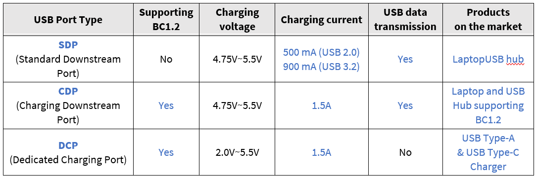
Table 1. SDP, CDP, DCP Comparison Chart
Five Steps to Check for BC1.2 Charging Support
How can a mobile phone that supports BC1.2 know whether it is connected to an SDP, a CDP or a DCP supporting BC1.2? Figure 1 (below) illustrates a simple flow, while Figure 2 offers a more detailed description.

Figure 1. 5 Simple Steps to Check for BC1.2 Charging Support
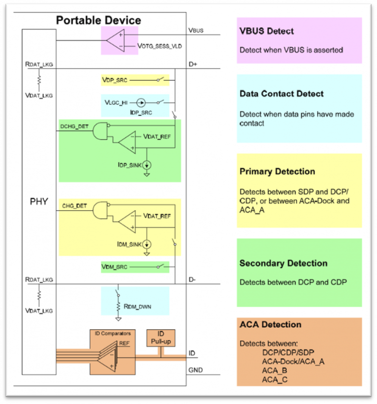
Figure 2. 5 Detailed Steps to Check for BC1.2 Charging Support
1. VBUS Detect:
The mobile phone connects to a USB charging port. When it detects a Vbus voltage which is greater than the internal effective voltage threshold, it means that the mobile phone is connected to an effective circuit.
2. Data Contact Detect (DCD):
The mobile phone detects whether the connected charging port supports BC1.2. The phone outputs current on D+ (IDP_SRC) and then detects the voltage value on D- to confirm whether the D+/D- pins are successfully connected. As the mobile phone is not required to support DCD, another mechanism is used: the mobile phone will enter Step 3 for detection after a period of time (TDCD_TIMEOUT). The advantage of DCD is that the mobile phone can enter Step 3 for detection immediately after judging that connection is successful, thus reducing waiting time.
3. Primary Detection:
The mobile phone detects whether the charging port connected supports BC1.2. That is to say, the mobile phone detects whether it is connected to an SDP, CDP or DCP.The mobile phone will supply a voltage (VDP_SRC) on D+ and then compare VDM and VDAT_REF on D-.
- If VDM is greater than VDAT_REF, it may be connected to a CDP or a DCP, and proceed to Step 4 for
- If VDM is less than VDAT_REF, it is definitely connected to an SDP and the process is complete.
4. Secondary Detection:
Secondary detection confirms whether the BC1.2 charging port connected to the mobile phone support USB Data transmission (DCP or CDP). The mobile phone will supply a voltage (VDM_SRC) on D-, and then compare VDP and VDAT_REF on D+.
- If VDP is greater than VDAT_REF, it is connected to a DCP
- If VDP is less than VDAT_REF, it is connected to a CDP
5. ACA Detection:
ACA Detection is conducted only for a portable device with a Micro-AB socket. The portable device detects whether it is connected to an ACA charging port and determines the device type. It mainly makes this determination by detecting the five different resistances on the ID pin.
How BC1.2 Mobile Phones Determine If They Are Connected via SDP, CDP or DCP
Case (I) BC1.2 mobile phone connects to SDP (no BC1.2 support)
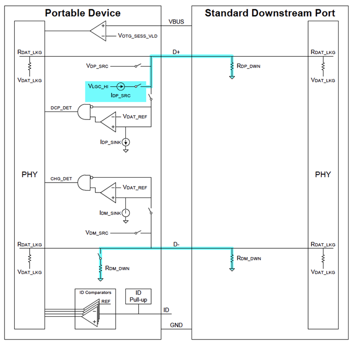
Fig. 3: SDP Detection
- The mobile phone (Portable Device) connects to SDP and detects connection to VBUS (VBUS > VOTG_SESS_VLD)
- DCD detection timeout
- The mobile phone supplies a voltage VDP_SRC (0.5V - 0.7V) on D+, connects to ground via RDP_DWN (14.25 - 24.8kΩ) on SDP, and then compares VDM and VDAT_REF on D-
- At this time, if VDM =0 V. If VDM (0V) is less than VDAT_REF (0.25V - 0.4V), it means it is connected to SDP, and that the process is complete
Case (II) BC1.2 mobile phone connects to CDP
Primary Detection, CDP Secondary Detection, CDP
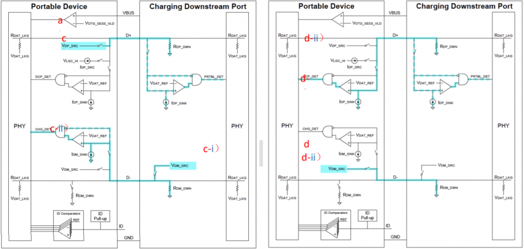
Figure 4. CDP Detection
- The mobile phone connects to CDP and detects a V BUS (V BUS > V OTG_SESS_VLD ) connection
- DCD detection timeout
- Primary detection (Figure 4 – left): The mobile phone supplies a voltage VDP_SRC (0.5V - 0.7V) on D+, and connects to ground via RDP_DWN (14.25 - 24.8kΩ) on CDP
- CDP detects D+=VDP_SRC (0.5V-0.7V), and then enables VDM_SRC (0.5V-0.7V) of CDP
- If the mobile phone detects D-=VDM_SRC (0.5V-0.7V), greater than VDAT_REF (0.25V-0.4V), it is connected to CDP or DCP
- Secondary detection (Figure 4 – Right): The mobile phone supplies a voltage VDM_SRC (0.5V-0.7V) on D-
-
- At this time, D+ ≈0 V, if the mobile phone DCP_DET detects that D+ is less than VDAT_REF (0.25V-0.4V), it is connected to CDP
- Then the mobile phone disables VDP_SRC and VDM_SRC, and keeps D+ and D- at low potential
Case (III) BC1.2 mobile phone connects to DCP
Primary Detection, DCP Secondary Detection, DCP
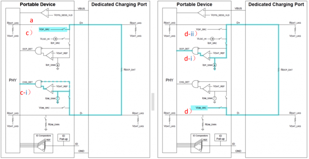
Figure 5.DCP Detection
- The mobile phone connects to DCP and detects to V BUS (V BUS > V OTG_SESS_VLD ) connection
- DCD detect timeout
- Primary Detect (Figure 5 – Left): The mobile phone supplies a voltage VDP_SRC (0.5V-0.7V) on D+, and connects to D- via RDCP_DAT (<200Ω) on DCP
- If the mobile phone detects D- ≈ VDP_SRC (0.5V-0.7V) greater than VDAT_REF (0.25V-0.4V), it is connected to CDP or DCP (maximum voltage drop of RDCP_DAT is 200Ω x 175μA= 0.035V)
- Secondary Detect (Figure 5 –Right): The mobile phone supplies a voltage VDM_SRC (0.5V-0.7V) on D-, connects to D- via RDCP_DAT (<200Ω) on DCP and enables IDP_SINK (25μA -175μA)
- If the mobile phone detects D+ ≈ VDM_SRC (0.5V-0.7V) greater than VDAT_REF (0.25V-0.4V), it is connected to DCP (maximum voltage drop of RDCP_DAT is 200Ω x 175μA= 0.035V)
- Then the mobile phone enables VDP_SRC.
BC 1.2 Test Items
The BC1.2 test is conducted mainly to confirm correct BC1.2 communication and Vbus power supply quality. The test items for CDP certification are as follows (see Table 2 below).
CDP test items for certification:
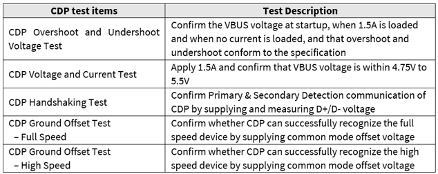
Table 2: CDP Test Items
DCP test items for certification:
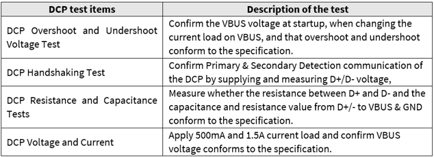
Table 3: DCP Test Items
Conclusion
USB Type-C Power Delivery's fast charging support meets modern needs of efficiency while also providing downwards compatibility with portable devices. Having a charging port defined by BC1.2 allows portable devices to draw more current to facilitate faster charging. By understanding the basic operating principles and test items surrounding BC1.2, manufacturers can minimize design problems and produce products that are in line with modern market demands.
References
- Battery Charging Specification, Revision 1.2, March 15, 2012
- USB Battery Charging 1.2 Compliance Plan, Revision 1.2, September 30, 2013
Author
Jimmy Lin, Test Engineer of GRL
Jimmy is a GRL Thunderbolt 3/4 and USB4® Certification Test Engineer, with four years of high frequency test experience. He is acquainted with test specifications and principles of Thunderbolt and USB and assists customers in solving challenging test problems and attaining certification.

Specifications and descriptions in this document can be subjected to changes by GRL without prior notice.
Release date: 2021/06/24 AN-210624-TW