Granite River Labs, GRL
Jimmy Lin 林致均
The latest USB4 Electrical Certification Test Specification Version 1.03 was released by USB-IF on June 8, 2022. Version 1.03’s most significant difference from the original Version 1.0 lies in the test item: USB4 Receiver Signal Frequency Variation Training Test.
This test item mainly measures whether a product’s receiver can maintain error-free connections when changes occur within the Spread Spectrum Clock (SSC) of the receiving signal. According to specifications outlined by USB-IF, a product is deemed to have passed the USB4 Receiver Signal Frequency Variation Training Test if it successfully registers a Bit Error Rate of less than 1E-6.
Version 1.03 evaluates receiver connection by simulating the re-timer’s operation process. As shown in the red area of Figure 1 below, data is first transmitted via the Local clock whenever a re-timer begins operating. During this period, frequency variation must be maintained around approximately 300ppm.
Once this frequency variation is achieved, the re-timer will switch over to use the Recovered clock for data transmission instead. This switching process is demarcated by the green area in Figure 1. By then, the re-timer will have entered a stable operation stage, as indicated by the blue area.
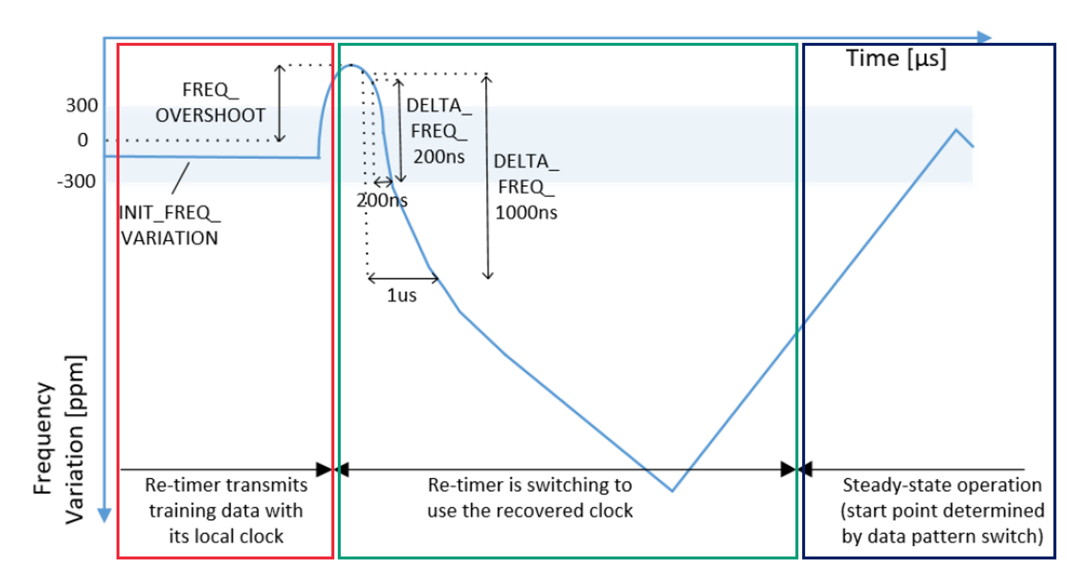 Figure 1: Changes in Re-timer Frequency Variation. Source: Universal Serial Bus 4 (USB4) Specification Version 1.0, May 2021
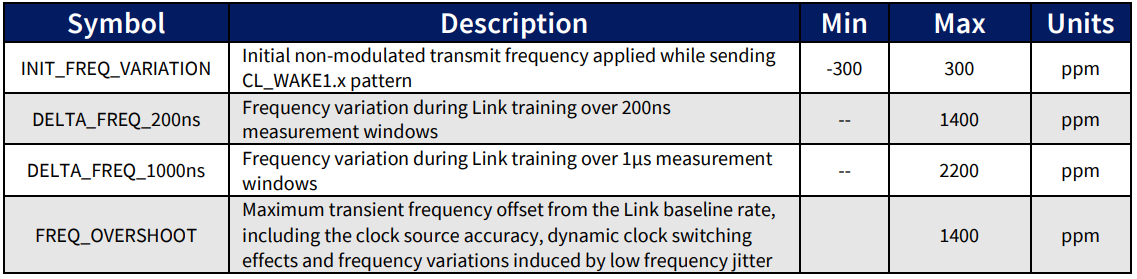 Table 1: Transmitter Frequency Variation Limits. Source: Universal Serial Bus 4 (USB4) Specification Version 1.0, May 2021
Now that the groundwork for USB4 Receiver Signal Frequency Variation Training Test has been laid, let us dive deeper to explore the differences between the testing methods of both Version 1.0 and Version 1.3.
USB4 Electrical Certification Test Specification Version 1.0 — Test approach
The specified test environment of USB4 Electrical Certification Test Specification Version 1.0 is the same as that of Receiver Tx BER Test TP3.
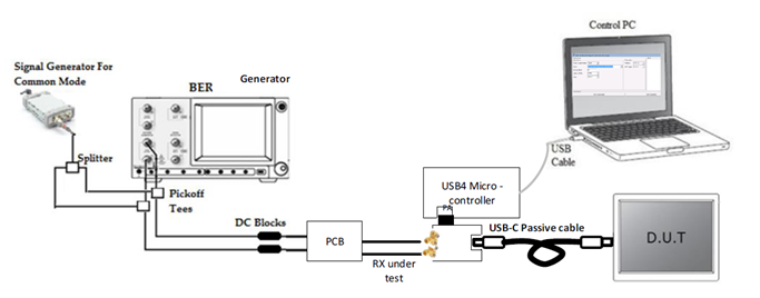 Figure 2: Diagram of Receiver Rx BER Test TP3 Test Environment. Source: Universal Serial Bus 4 (USB4) Router Assembly Electrical Compliance Test Specification Revision 1.0, June 2020.
The Version 1.0 test is conducted by using first Receiver Rx BER Test Case 2 to verify settings at PH 1MHz while also turning off the module that generates SSC in BERT. Following which, the frequency of PJ must be changed to 0.4MHz. Jitter size will vary depending on whether Gen2 (22.4UI) or Gen3 (44.8UI) USB4 is being tested, while remaining settings remain unchanged.
Once the test environment setup has been completed, the Electrical Test Tool (ETT) will be used to perform the BER test, where a test time of 10 seconds will be used to determine whether the BER after the test is less than 1E-6. This test item must be executed at speeds supported by the two lanes on the USB4 Type-C port.
USB4 Electrical Certification Test Specification Version 1.3 — Test approach
In contrast, test specifications of Version 1.03 require tests to be conducted to environment parameters outlined in Case1 and Case2. During calibration, open the corresponding Case in the PJ 100MHz verification settings and change the pattern used to PRBS15. Then, turn off the original SSC module and use the SSC module designed for Clock Switch instead. Once that is done, begin setting up parameters as shown in Figure 2 and Figure 3.
It must be noted, however, that parameters shown in the figure are set for Rounded Speed (10G & 20G), rather than Legacy Speed (10.3123G & 20.625G), which will not be used in this test.
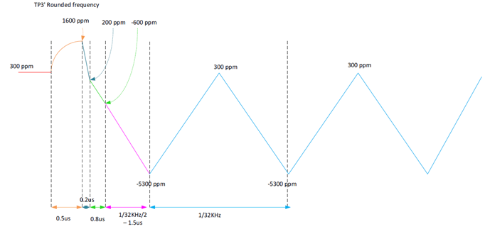 Figure 3: Case1 SSC Module parameter settings. Source: Universal Serial Bus 4 (USB4) Router Assembly Electrical Compliance Test Specification Revision 1.03, June 8 2022.
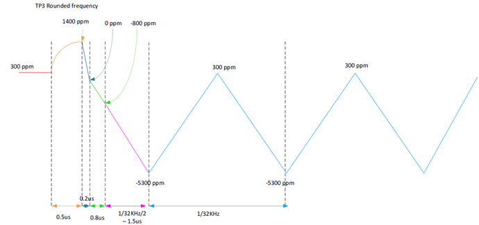 Figure 4: Case2 SSC Module parameter settings. Source: Universal Serial Bus 4 (USB4) Router Assembly Electrical Compliance Test Specification Revision 1.03, June 8 2022.
Once you’re ready to start testing, open the environment set up above and turn off the SSC module designed for Clock Switch. To perform BER testing, click on Execute ETT. This will cause a window message that reads “to turn on clk-switch over the Generator” to pop up. After clicking confirm, turn on the SSC module for each CLock Switch and start the test.
Tests last for 10 seconds, and BER will be recorded after each test to determine if it fits the passing criteria of less than 1E-6. Because the Version 1.03 specification requires testing speeds that are supported by two lanes on the USB4 Type-C port, the test must be repeated 20 times to obtain results based on the highest error count. The good news is that this test frequency requirement has since been reduced to 5 times with the new Intel Streamline standard that accounts for test time.
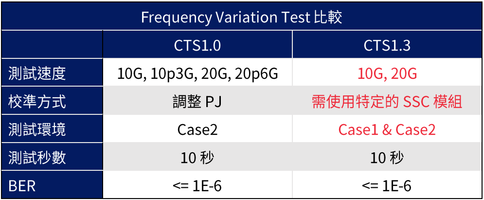 Table 2: Differences in Frequency Variation Test under CTS 1.0 and CTS 1.3
Become certified under the new V1.03 USB4 Receiver Signal Frequency Variation Training Test with GRL
Signal attenuation continues to be challenging among modern laptops, which are designed in a way that creates long distances between CPU and the connector. Re-timers therefore continue to play a pivotal role by offering more design flexibility to circuits that they are added to.
Version 1.03 of the USB4 Receiver Signal Frequency Variation Training Test has made it possible to assess re-timer behavior more accurately. Combined with GRL’s rich USB certification experience, manufacturers of USB4 integrated products can continue to obtain USB4 certification that will not only enable them to break into new markets, but provide quality user experience for their end customers.

References
- Universal Serial Bus 4 (USB4) Router Assembly Electrical Compliance Test Specification Revision 1.03, June 2022
- Universal Serial Bus 4 (USB4) Router Assembly Electrical Compliance Test Specification Revision 1.0, June 2020
- Universal Serial Bus 4 (USB4) Specification Version 1.0, May 2021
About the Author
Jimmy Lin, Technical Engineer of GRL Taiwan
Engineer responsible for GRL Thunderbolt ¾ and USB4 certification tests, with over four years of experience in helping customers resolve test problems and abide by specifications and principles of high-frequency tests.
Specifications and descriptions within this article are subject to change without prior notice.
Original Chinese Version first released on 2022/11/08 AN-221108-TW