Granite River Labs, GRL
Sandy Chang 張靜宜

Due to limitations in the longest passive cable at the time of writing, applications that require high-speed cables that support more than 40G (20Gx2) and are longer than 1 meter in length require external connections to large scene, VR applications, or active cables to function.
For information on passive cable specifications and test procedures, please refer to A Proactive Approach to USB4® Passive Cable Testing and Certification.
Introducing the three different varieties of USB Type-C active cables
USB Type-C active cables can be divided into three main categories:
- USB 3.2 Short Active Cable
- USB4 Short Active Cable
- USB 3.2 Optically Isolated Active Cable (OIAC)
In particular, OIACs are fiber optic cables that can extend up to 50 meters in length. At present, OIACs are defined to support up to USB 3.2 Gen2 speeds (with exception of USB 2.0 and VBUS power supply). OIACs are typically used in industrial applications, medical treatment applications, machine vision, remote sensors, professional videos, and more. An upcoming cable that is still in development, the USB4 Linear Optical Active Cable, has yet to be defined.
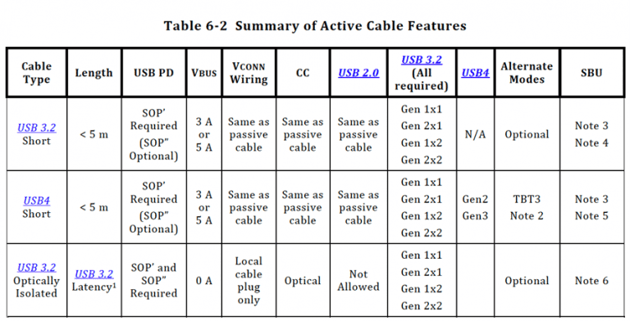 Table 1: Key features of USB short active cables
Defining features of USB 3.2 Short Active Cable
- Length of not more than 5 meters
- Support Full-Feature Type-C and USB PD 3.0 eMarker
- Can be plugged in both normal and reverse orientations
- Can be divided into USB 3.2 and USB4 active cables according to capabilities:
- Must support USB 3.2 Gen 2×2(10GHz dual channel)
*Active cables that only support single channel(x1)do not qualify - Optional alt-mode support
- Must support all USB 3.2 and USB4 speeds(dual-lane)
- Must support TBT3 Alt-Mode
- Must support USB 3.2 Gen 2×2(10GHz dual channel)
- USB 3.2 active cable:
- USB4 active cable:
- Wire requirements of Vbus, Vconn, CC and USB 2.0 are consistent with requirements for passive cables
- Active cables must be powered by Vconn
All active cables consist of a repeater component such as a re-timer or re-driver for the purposes of facilitating high-speed signals such as Tx1, Tx2, Rx1, and Rx2. Out of all the repeater components, re-timers tend to be the most expensive and complicated to maneuver. On the other hand, re-driver based linear re-driver cables (or LRD for short) are lower in complexity, power consumption, and cost.
Interestingly, LRDs were the first to launch in the market despite being added to the USB ecosystem and incorporated into the USB Type-C specification at a later stage. Today, cables such as Thunderbolt 4 that support 40Gbps two meters are formed by LRD cables that support USB4.
Architecture of Linear Re-Driver Cable
LRD cables are made up of Rx Equalizer and Output Driver, the components responsible for compensating cable loss, adjusting DC Gain, and calibrating the output pre-emphasis and signal size, as illustrated in the figure below.
.png?width=639&name=%E5%9C%96%E7%89%873%20(2).png) Figure 1: Architecture of Linear Re-Driver Cable
Figure 1: Architecture of Linear Re-Driver Cable
LRD cable design considerations
Because LRD cables do not feature Clock Data Recovery (CDR), jitter and noise received at cable input is inevitably transferred to cable output. Rx EQ may further exacerbate this problem by amplifying high-frequency noise, resulting in discontinuous impedance in the paddle card from the addition of active components such as AC Common mode exceeding specifications.
To prevent excessive noise and jitter, the following points should be considered whenever LRD cables are designed:
- High-frequency noise caused by cables
- Whether the cable’s internal EQ and signals are insufficient, properly balanced, or over-balanced.
- Impedance matching of additional components inside the active cable
- P-N skew of cable high-speed pair
Introducing LRD cable function support and eMarker
According to the USB Type-C Connector & Cable Rev 2.1 specification (shown in Table 6-3 below), both USB4 passive cables and active cables must be capable of supporting USB4, USB4, USB2, and TBT3. OIAC is the exception to this rule.
What sets the USB4 LRD cable apart is the active cable. However, eMarker must declare USB4 LRD cable as a passive cable (011b) in the ID Header VDO setting of eMarker using Passive Cable VDO. Because the LRD cable was included in the USB specification at a later stage, it must be declared as passive in order to remain compatible with TBT3 products on the market.
That said, TBT3 Discover_SVID (0x8087) will continue to be performed during the USB4 Discover communication process to determine whether it should be considered as a “USB4 with TBT3 Gen3 Active Cable”.
.png?width=658&name=%E5%9C%96%E7%89%874%20(2).png) Table 2: Overview of USB4 cables
Table 2: Overview of USB4 cables
USB-IF releases new USB4 Logo and Icon
USB-IF held the USB DevDays 2021 seminar in Seattle last week, where the new USB Type-C Cable logo and icon was released in conjunction with the Extended Power Range specification. These visual markers are designed to allow users to quickly identify USB products supported by speed and power.
Along with this release comes the phasing out of cables that originally support 100W (20V/5A). Additionally, cables that support 5A are now required to support EPR 240W (48V/5A).
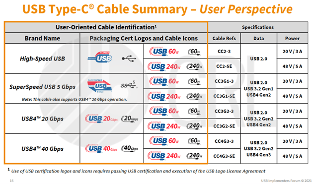 Table 3: New Certified USB Type-C Cable logo and Icon. Source: USB-IF Logo License – USB4® Logo Usage Guidelines.
Examples of the new USB4 cable logo:
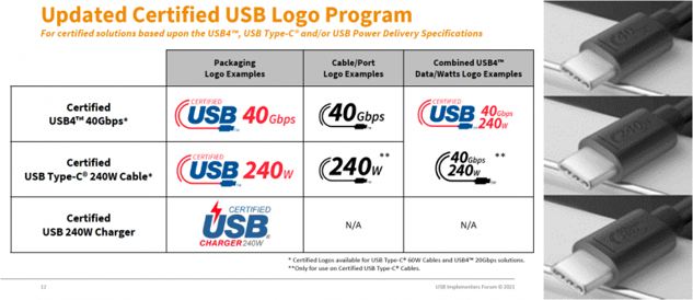 Figure 2: USB Type-C EPR Cable logo and Icon. Source: USB-IF Logo License – USB4® Logo Usage Guidelines.
The LRD cable active cable adds the Re-driver as an active component to the cable, allowing it to support longer lengths. Under certification testing, LRD cables should provide the same performance levels as that of passive cables under the same test environment settings, or even better.
LRD test certification items
- USB-C Functional Test
- USB PD E-Marker Test
- Active Cable Power:IR Drop and Power Consumption
- Thermal Overheat Safeguard
- LRD Electrical Characteristics Test
- LRD Cable Compatibility Test (pending approval)
Details of the LRD Cable Electrical are as follows:
1. USB-C Functional Test
The following test details abide by the USB-C function test specification:
- TD 4.1.3 Unpowered Cable Test
- TD 4.13.5 Cable EnterUSB and Data Reset Test
- TD 4.14.x
- TD 4.14.1 Cable Vconn Swap Test
- TD 4.14.2 Cable Reset Test
- TD 4.14.3 Cable Alternate Mode Test
- TD 4.14.4 Cable USB 3.2 Test
- TD 4.14.5 Cable USB4 Test
2. USB PD: E-Marker Test
The three major cable-related test items outlined by USB PD CTS are as follows:
- Common Procedures and Checks
- Physical Layer Specific Tests
- Protocol Specific Tests
All LRD Cables must support TBT3, and this is confirmed via responses in TBT3 and SOp.
- Cable SOP’ Discover Identity response
- [ID Header VDO] B26 (model operation) set to 1b (alt mode)
- [ID Header VDO] B29..27 (product type)set to 11b (passive cable)
- [Cable VDO] B2..0 (USB highest speed) set to 010b (USB3.2/USB4 Gen2)
- Cable SOP’ TBT Discover Mode VDO response
- .19 (rounded/rounded & none) set to 01b (both)
- B21 (Optical/none) set to 0 (none)
- B22 (Re-timer/Re-driver) set to 0b (Re-driver)
- B23 (Uni/Bi-directional) set to 1b (Uni)
- B25 (Active/Passive) to 1b (Active)
3. Active Cable Power Requirements
3.1. VBUS and IR Drop of Ground Cables is the same as that of passive cables
- VBUS IR Drop:≤500 mV
- Ground IR Drop:≤250 mV
3.2. Power supply of the active cable is mainly through VCONN, with maximum power consumption limited
- VCONN power consumption ≤1.5W
4. Thermal Test
For safety reasons, active cables must be equipped with temperature sensors. This will activate a safety mechanism where data transmission in USB 3.2/USB4 cables stop once temperature of the plastic shell reaches 80˚C or the metal surface reaches 55˚C.
In addition, the shell surface of an active cable plug must not exceed an ambient temperature of 30˚C. The metal shell temperature must not exceed a temperature of 15˚C either.
The main factors influencing surface temperatures of active cable plastic shells are the operating temperature of the connected Host and Device motherboards, active components in the cable, and surrounding ambient temperature. In the actual certification test, thermal tests are divided into two main components, surface temperature and overheating protection (also known as Thermal shutdown). The way this test environment is simulated is shown in the figure below:
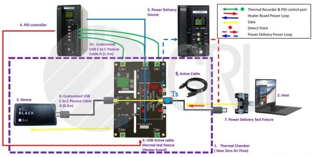 Figure 3: Schematic diagram of overheating protection test connection
4.1 Surface Temperature (Ts)
At room temperature, use the Thermal Test Fixture Heater board to simulate the Host/Device main board (as shown in Figure 3). Allow the TMB to heat up to(TA+ 25˚C), then connect the active cable and perform the full load setting from Host to the Device, including simultaneous high-speed data transmission, and PD 100W load.
Once that is done, the infrared camera will be activated to search for the area of highest temperature within the cable plug (Figure 4). A “Thermal Couple” patch is then pasted on the identified location for temperature testing later (Figure 5). This test component will be successfully cleared if the plastic shell’s surface temperature is such that TS < TA +30˚C.
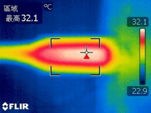
Figure 4: Infrared camera finds area of highest temperature
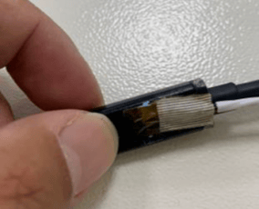
Figure 5: “Thermal Couple” patch being pasted onto highest temperature area identified.
4.2 Thermal Shutdown
Test environment settings for overheating protection are the same as those outlined in 4.1. In addition, a heating patch is wrapped around the cable plug’s plastic shell (Figure 6). This test component will be considered to be successfully cleared once the data transmission across USB3.2/USB4 cable stops when the heating patch reaches 85˚C.
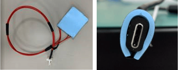 Figure 6: Flexible heating patch
For more information on Active Cable Thermal accessories, please contact: Od.Liao@luxshare-ict.com
5. Electrical Characteristics Test
For LRD cables, passive cables are still used in USB 2.0, SBU, and CC cable configurations. Therefore, the test methods and specifications remain the same as passive cables. The high-speed signal pair Tx1/Tx1/Tx2/Rx2 are equipped with Re-driver active components. Test specifications are in accordance with LRD Active Cable CTS version 0.8. The main three test items are as follows:
- Frequency Domain Test
- Time domain – Cable Stand-Alone Test
- Time domain – Cable Output Eye Test Test
5.1 Frequency Domain Test
– Integrated Return-Loss (IRL)
– Integrated Multi-Reflection (IMR)
– Channel Operation Margin (COM)
Frequency domain test items use the same test methods as passive cables, where the vector network analyzer (VNA) captures S parameters and a total of 8 S4P files of high-speed differential pairs (Tx1/Rx1/Tx2/Rx2, bidirectional) via the Get_iPar_v0p91a software for analysis.
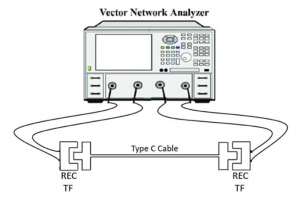 Figure 7: S-parameter connection diagram for vector network analyzer (VNA) acquisition
5.2 Time Domain - Cable Body Test
– Cable ILfit Mask(DC/f1/Nq/f2/f3/WB):insertionloss
– OUTPUT_NOISE(𝝈𝒏):Standard deviation (excluding non-linear noise)
– SIGMA_E(𝝈𝒆):Standard deviation of non-linear noise output
– Cable CM_NOISE:AC common mode
With exception of system ISI and jitter, cable body tests focus on the cable’s insertion loss, output noise, non-linear noise, and AC common mode. As shown in the figure below, the signal generator output at TP2 shows Pattern Swing with no Jitter, SSC, nor Tx EQ settings (e.g. “Pattern: PRBS15, Swing 800mV, SSC off, Jitter off, Preset 0”).
To execute the test, first connect the Worst-Case passive cable to the test equipment for the oscilloscope to capture the waveform *.bin. Then, replace the Worst-Case passive cable with the LRD cable for testing, analyzing the parameters before comparing the test results of the LRD cable — which must be equal to or better than that of a passive cable. Make sure that the test covers all three speeds including USB4 Gen2/Gen3, and USB 3.2 Gen2.
*Note that Worst-Case passive cable refers to passive cables with the largest insertion loss within the cable specification. Examples include 1m USB 3.2 Gen2 passive cables, 2m USB4 Gen2 passive cables, and 0.8m USB4 Gen3 passive cable cables.
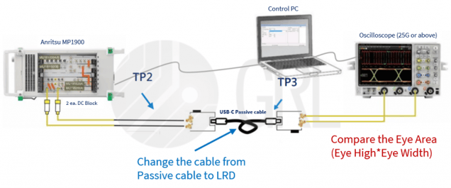
Figure 8: Diagram of cable body test connection
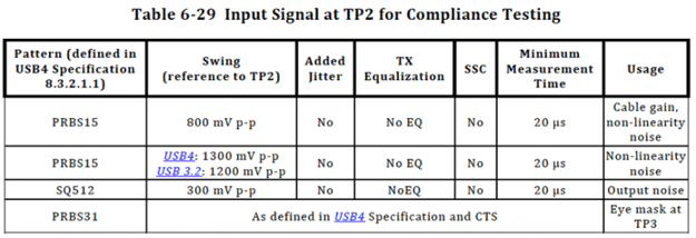 Table 4: Environment setting requirements of cable body testing
5.3 Time Domain - Cable Output Eye Diagram Test
5.3.1. USB4 Gen2/Gen3 Test
Test environment for the cable output eye diagram test is the same as the USB4 Host/Device Rx receiver certification test environment. It is necessary to perform USB4 Rx test environment correction prior to commencing the test. This can be done directly through the GRL-USB4-Rx Test APP, which automatically controls the Anritsu MP1900 Pattern Generator and works with Keysight or Tektronix oscilloscopes for USB4 Rx test environment calibration.
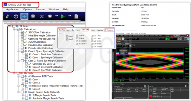 Figure 9: GRL USB4 Rx automated test app
Once calibration is complete, connect the “Worse Case passive cable” to the test equipment. Ensure that test condition settings include outputting PRBS31 in the Pattern Gen, and that the setting of USB4 Preset is in place (with 16 groups in total).
After the signal passes through the cable, five waveforms will be captured on the oscilloscope. Each high-speed pair must capture 80 waveforms. Following that, remove the passive cable and replace it with an LRD cable to capture waveforms on the oscilloscope under the same conditions. Use the USB4 SigTest software to perform eye diagram, eye width, and Eye Zone Test Analysis.
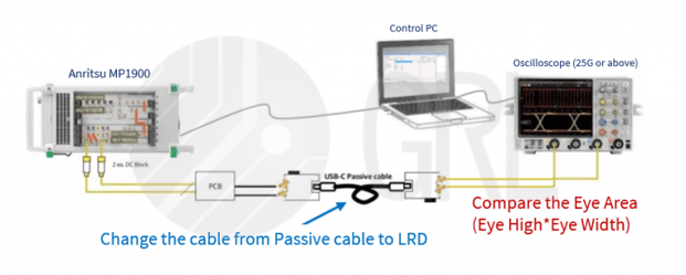
Figure 10: Diagram of USB4 Gen3/Gen2 cable output eye test connection
Assessment of USB4 Gen2/Gen3 test results (Average of 5 captures):
Area of the best eye diagram of LRD Cable ≥ Area of the best eye diagram of passive cable
Eye width of LRD cable ≥ 0.9 * Passive cable eye width
5.3.2. USB 3.2 Gen2 test:
Test environment settings are similar to that of USB 3.2 Rx receiver certification. First, calibrate settings according to what is shown in Figure 11. The Anritsu MP1900 Pattern Generator can be automatically controlled through the GRL-USB3-Rx Test APP, which can then be used with Keysight or Tektronix.
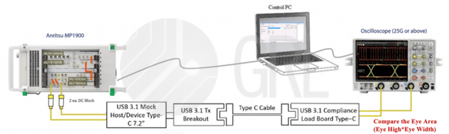 Figure 11: Diagram of USB 3.2 Gen2 cable output eye diagram test connection
After calibration, select Rx to calibrate the environment of Pj@100MHz while maintaining the test conditions of USB 3.2 Gen2 Rx. Once Pattern Gen passes through the fixture and LRD cable, the oscilloscope will capture five waveforms and use USB4 SigTest software and seven CTLE templates for analysis.
*Note that USB4 SigTest only has one CTLE-5dB template initially, and needs to be manually set to complement the CTLE-0dB ~ CTLE_6 dB template.
Assessment of 3.2 Gen2 test results (Average of 5 captures):
Area of best eye diagram of LRD cable ≥ Area of best eye diagram of passive cable
Eye width of LRD cable ≥ 0.9 * passive cable eye width
Test and certify USB Type-C cables with technical experts
USB Type-C continues to be widely used in computers and related peripheral devices, passive cables, and active cables. Though only some USB Type-C cables support USB 2.03 and charging, while others support USB 3.2 and USB4, it must be stressed that these cables are all considered to be USB Type-C connectors.
In efforts to improve the user experience, the USB Association has strengthened its commitment towards creating a Type-C cable standard that meets all application requirements. For active cables, specifications must support bidirectional transmission, positive and negative insertion, and dual channels (x2).
The USB4 LRD active cable serves as a prime example of this by satisfying support for USB4, USB 3.2, USB 2.0, Thunderbolt 3, PD charging, and more within one cable. The largest difference between USB Type-C active cables and passive cables is the presence or absence of active components, which results in different methods being used for the testing of high-speed differential signals.
Active cable tests use the existing high-frequency test method of USB4 Host and Device, with test environments and methods being relatively complicated. GRL smoothens the testing process by providing an automated test solution for USB4 testing to adjust EQ, Gain, and other parameters to assist customers in debugging. In addition, our seasoned testing team also provides end-to-end support for testing and certification services in USB4 Host and Device, USB4 Passive Cable, and USB4 Active Cable.
Expedite the process of cable development and USB4 certification with GRL’s professional certification team located worldwide. Contact us today for a one-to-one consultation.
References
- USB Type-C Cable and Connector Specification, Release 2.1, May 2021
- USB Type-C Connectors and Cable Assemblies CTS, Revision 2.1b, June 2021
- USB4™ Thunderbolt3™ Compatibility Requirements Spec, Version 1.0, January 2021.
- USB4™ Thunderbolt3™ Compatibility CTS, Revision 1.0, January 2021.
- USB Power Delivery CTS, Revision: 1.2, Ver 2, June 20, 2021
- USB Type-C Functional Test Specification, Chapter 4 and 5, May 23, 2021, Rev 0.88
About the Author
GRL Taiwan Technical Director Sandy Chang
An expert in the field of high-speed interface testing, Sandy has over 10 years of professional experience dealing with Thunderbolt™ 4, USB4, USB3, DisplayPort, HDMI, PCI Express, and other industrial technologies. She currently serves as the technical director of GRL where she leads test teams.

Specifications and descriptions in this document are subject to change without prior notice.
Original Chinese (Traditional) version release date: 2021/10/06 AN-211006-TW