Granite River Labs (GRL)
By Cindy Chang – Test Engineer, GRL (Taipei)
In the past, electronic devices were mainly charged with interfaces provided by the manufacturer, which ended up in landfill when the product was replaced. The popularity of USB improved that picture, however capacity remained limited to a maximum of 7.5W (5V 1.5A) for USB Battery Charging 1.2 (BC1.2), and the devices themselves took a significant period of time to recharge.
The release of the USB-IF (USB Implementers Forum) USB Power Delivery Specification Version 1.0 in 2012 increased power supply capacity to a maximum of 100W (20V 5A). Following updates and the addition of more functions, the latest version is USB Power Delivery Specification Revision 3.0 (hereinafter referred to as PD or PD Spec).
Following current consumer trends, the Type-C interface has gradually become the mainstream choice, and most products now support PD. In these products, the Configuration Channel (CC) pin is used for transmitting PD communication messages and protocols and supplying power through the VBUS pin.
USB Type-C® Architecture (Source/Sink Detection)
From a power supply end and power consumption end perspective, the role of power can be broadly divided into three main types:
| Power Role | Definition |
| Source | For the power supply end with power supply capability, Rp is set on the CC pin |
| Sink | Rd is set on the CC pin of the power consumption end |
| DRP | To simultaneously enable Source and Sink, both Rp and Rd should be set on the CC pin |
Table 1. Power Roles
The docked ends are detected via CC and VBUS to see if a suitable device is connected to:
- Source: Monitors the CC pin voltage. When source detects Rd on the CC pin, it means Sink is connected and Source will output 5V on VBUS
- Sink: Detects VBUS. When the voltage is 5V, it means Source is connected
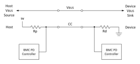
Figure 1: USB Type-C Connection Before PD communication (Source: USBType-C Cable and Connector Spec)
PD Architecture
Taking the Source end as an example, the Device Policy Manager is mainly responsible for monitoring the overall usage of the device. Its duties include managing the Power Source and USB-C® Port Control modules and cooperating with the Policy Engine to adjust the power distribution. Each port is connected to the device protocol according to the resources allocated. USB-C Control controls the Source/Sink Detection (described in the previous section). After that, PD behavior is jointly controlled by the Physical Layer (PHY Layer), Protocol and Policy Engine. Finally, the power is supplied to the other party through VBUS by Power Source.
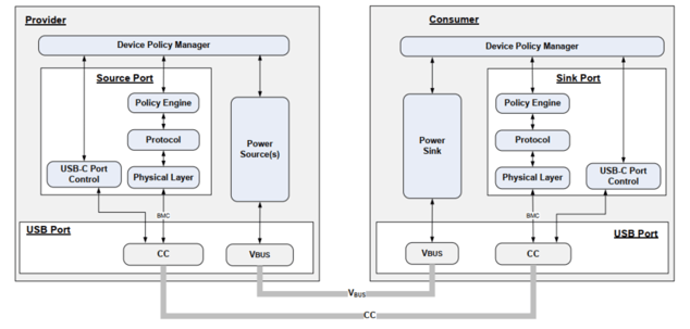 Figure 2. USB PD Structure (Source: PD3.0 spec)
- Policy Engine
The state of individual ports within the Device Policy Manager is provided, so that the Policy Manager can integrate and update the device state in real time and redeploy resources to each port. It determines how to send and respond to the received PD message according to the policy and instructs the Protocol Layer to construct the message.
- Protocol Layer
Sending message end: Receives the instruction from the Policy Engine, constructs the required message and sends it to the PHY Layer. It then confirms that the message has been sent correctly through GoodCRC and returned from the other party. Otherwise, it will be regarded as a transmission failure and the Retry mechanism will be triggered.
Receiving message end: Receives the message from the PHY layer, interprets the message and reports it to the Policy Engine. Before responding, this end will first construct a GoodCRC message and let the PHY send it back to the other party, indicating that the message has been correctly received and interpreted.
At the same time, the Protocol Layer of each device needs to calculate whether the other party replies with a corresponding response within the required time (Timer check).
If any error is detected in the above confirmation, Protocol Layer of either party can initiate the Reset mechanism to adjust the state:
| Reset Type | Purpose |
| Soft Reset | Protocol Layer reset (including timer, counters and states). Does not affect the agreed Power role, Data role and the agreed Voltage and Current before Reset. |
| Hard Reset | Will be used if Soft Reset cannot resolve the current error. Except for the Power role, all the PD protocols are restarted. In this process, the Source end will temporarily turn off the VBUS voltage to 0V, then turn it on until 5V and reconnect with the Sink protocol. |
| Cable Reset | Only the DFP on the Host end can initiate a Cable Reset to reset communication with the cables. |
| Data Reset | Reset the USB data device. After a reset, devices at both ends will not be in Alternate Mode. |
Table 2. Reset Types
- PHY Layer
PHY reprocesses the message sent from the Protocol layer and composes a complete message together with SOP*, CRC, EOP and Preamble encoded in 4b5b mode. Then it is sent to the other party in BMC mode through CC.
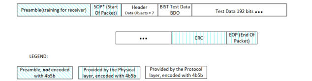
Figure 3: PD Message Format (Source: PD3.0 spec)
When it receives a message, PHY will first verify it by conducting a CRC (cyclic redundancy check). If the message is correct, it is sent on to the Protocol Layer at the receiving end.
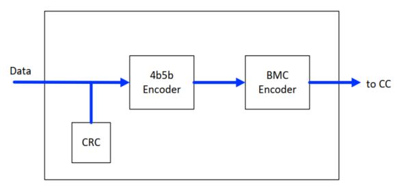
Figure 4: PHY Layer Message Transmission Flow (Source: PD3.0 Spec)
Taking the Source Capabilities message as an example, Figure 5 (below) briefly shows the sending end, receiving end and message transmission flow of the above content:
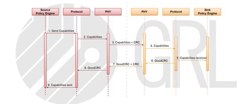
Figure 5: Source Capabilities Messages
Figure 5 shows that the PD messages of the devices at docking ends are transmitted by the same route (CC). To avoid sending messages at both ends at the same time, Source Protocol has a Collision Avoidance mechanism which tells Sink whether it can respond only to Source messages by instructing PHY to control Rp settings.
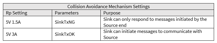
Table 3: Collision Avoidance Setting
PD Protocol
1. SOP* Communication
Before learning how to communicate, it is important to understand that the objects of PD message transmission can be divided into three types – SOP, SOP' and SOP".
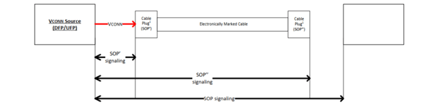
Figure 6: SOP/SOP'/SOP'' Communication Diagram (Source: PD3.0 Spec)
SOP is used for messages between Source and Sink. SOP' is used for messages close to Vconn Source (for supplying power to e-Markers in cables), and SOP" is used for messages delivered to the cable's far-end e-Marker.
* Not every cable is equipped with an e-Marker. However, according to the PD Spec rules, if any cable supports SuperSpeed or a current greater than 3A, there must be an e-Marker.
2. Implicit PD Contract
The Source/Sink power supply protocol is subject to intermediate cable conditions. For example, if the Source current supply is up to 5A, and the cable used can only support a maximum current of 3A, then the Source cannot create a protocol with Sink. Usually, Source will first send a Discover ID Request in the form of SOP' and read the cable information through the Discover ID ACK returned by the e-Marker.
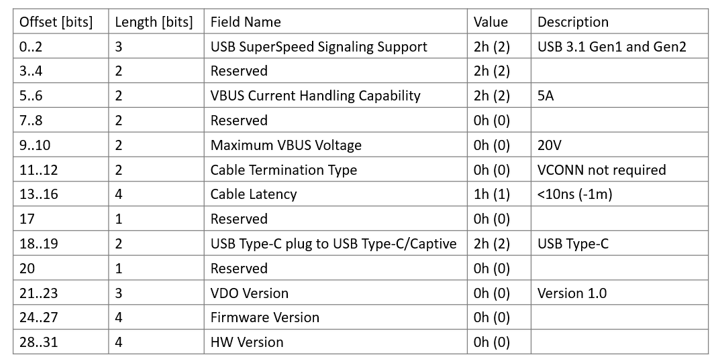 Figure 7: Analyzing the Discover ID ACK by GRL-A1
Source will send Source Capabilities to Sink to indicate the power supply capacity at the current state, referring to the conditions that the cable can support. Sink will select from the conditions and return a Request to Source for the required voltage and current. After receiving confirmation for supplying power at this condition, Source will reply Accept, and send PS RDY once it is prepared. At this step, the Implicit PD Contract is complete. After that, the two parties can renegotiate a new PD contract depending on the situation.
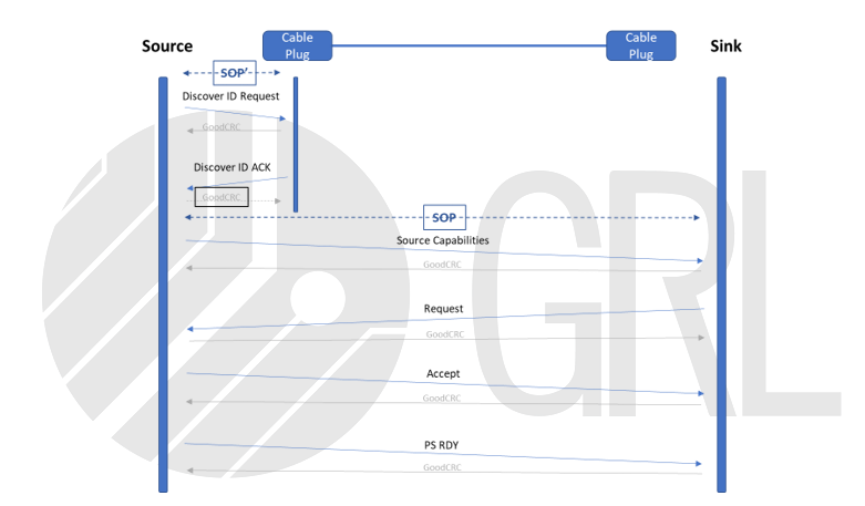
Figure 8: Implicit PD Contract Flow
Source Capabilities
The PD Spec also contains relevant chapters to explain the rules for the Source Capabilities specifications. The following are drawn from the PD 1.0 to PD3.0 specifications.
-
USB PD 1.0
There is no mandatory specification for the power supply end. Several recommended settings are listed, referring to the charging requirements of most products.
*To comply with international safety standards, the power supply capacity is limited to 100W, and the current is limited to 5A.
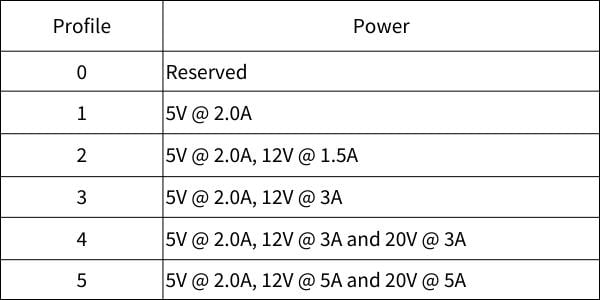
Table 4: PD 1.0 Recommended Power Supply Specifications (Source: PD1.0 Spec)
-
USB PD 2.0
Following the introduction of USB PD 2.0, the specification requires the power supply end in products to meet certain conditions (see Table 5 below). For example, if the maximum power is 36W, then it is necessary to set a combined power supply capacity of 5V 3A, 9V 3A and 15V 2.4A. This condition will be listed in the PDO (Power Data Object) field in Source Capabilities. Each product can add other combinations according to demand, except for the ones in the table, which are limited to 7 groups.
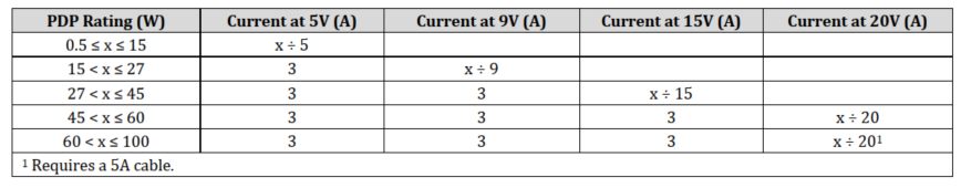
Table 5: PD2.0 Power Supply Specifications (Source: PD2.0 Spec)
* Since August 2020, USB-IF has terminated all certifications that only support products featuring PD2.0 or below.
-
USB PD 3.0
The power supply specification for USB PD 3.0 is as follows (see table 6), and an optional PPS (Programmable Power Supply) function is added. In PPS mode, the voltage can be adjusted by 20 mV/step, and the voltage range is extended to 3.3 V to 21 V. This technology can output large currents at lower voltages and greatly improves charging efficiency.
To distinguish the new PPS mode in PD3.0 from the existing PD2.0 mode, PDO can be divided into according to the following rules:
- Fixed Supply PDO (usually called Fixed PDO) refers to fixed voltage output mode.
- Augmented PDO (usually called APDO) means that the output voltage can adjust within a certain range under PPS mode.
Similarly, taking 36W as an example, if a product is required to support PPS (optional), it must include:
- Fixed PDO:5V@3A、9V@3A、15V@2.4A
- APDO:3V ~ 11V (9V Prog)@3A、3.3~16V (15V Prog)@2.4A
Since the 5V Prog is covered by the 9V Prog specification, if the two APDO settings are the same, the 5V Prog can be skipped and only 9V Prog needs to be listed.
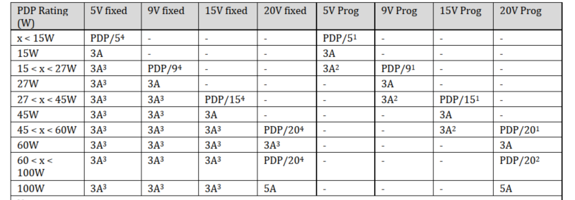
Table 6: PD3.0 Power Supply Specifications (Source: PD3.0 Spec)
References
- USB Type-C® Cable and Connector Specification Revision 2.0
- USB Power Delivery Specification Revision 1.0 Version 1.2
- USB Power Delivery Specification Revision 2.0 Version 1.3
- USB Power Delivery Specification Revision 3.0 Version 2.0
Author
Cindy Chang – Test Engineer, GRL (Taipei)
A graduate of the Department of Materials at National Cheng Kung University, Cindy Chang has more than three years of Power Delivery-related testing experience and is familiar with a variety of test specifications, such as Thunderbolt PD, USB-IF PD Compliance, and Qualcomm Quick Charge (QC). As a Test Engineer with GRL Taipei, she is responsible for helping customers to solve PD problems and obtaining certification.