Telecom, as services and technology, has become a decisive tool realizing a nation’s social-economic objectives.
The Department of Telecommunications (DoT), Government of India established the Telecommunication Engineering Center (TEC) as a body responsible for drawing up standards and requirements for telecom equipments, services, and networks.
Based on the defined standards and requirements, the Telecommunication Engineering Center (TEC) issues TEC certificates to equipments, services, and networks deemed eligible for use in India. The certification has become a mandated process under the Mandatory Testing Certification of Telecommunication Equipment (MTCTE) regulations to certify telecommunication equipments entering in India.
Requisites of MTCTE
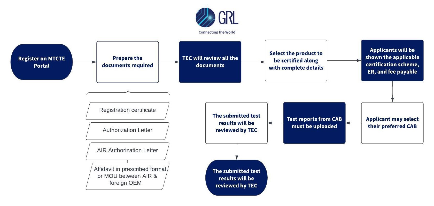
Under MTCTE regulations, any original equipment manufacturer or importer who wishes to sell, import, or use any telecom equipment in India must be certified by the TEC. The testing is to be carried out in conformance to essential requirements for the equipment as laid out by IEC/ISO 17025 accredited labs designated by TEC.
The Testing and Certification framework requires that all telecom equipment entering India meets the essential requirements under:
(b) Safety
(c) Technical requirements such as wireless, IPv4, IPv6, optical parameters
(d) Other requirements
- Energy
- E-Waste
- Wireless (WPC)
The main objectives of the certification process are as follows:
- To prevent any telecom equipment from degrading the performance of the existing network upon introduction
- End-user safety
- Protection of users and the general public by ensuring that radio frequency emissions from equipment do not exceed prescribed standards
- Compliance with the relevant national and international regulatory standards and requirements
EMI/EMC
Electromagnetic interference (EMI), also known as radio frequency interference (RFI), mainly occurs when electromagnetic energy disrupts the operation of an electronic device. This can be caused by natural occurrences or human error.
Electromagnetic compatibility (EMC) is the ability of a device to function as intended in an environment with other electrical devices or sources of EMI without affecting the other devices.
EMI can be trivial in some cases and severe in others, so it is vital to ensure EMC requirements are met. Compliance to EMC requirements can be achieved by adhering to the requirements defined in TEC's Essential Requirements. These requirements, in turn, refers to national and international standards such as CISPR 32 and IEC/EN 61000 series of standards.
Safety
Safety is a crucial criterion that cannot be taken lightly by manufacturers. It is imperative for them to adhere to all safety regulations established by the TEC under MTCTE. An electronic or electrical equipment must provide protection against various safety hazards, including electric shocks, harmful radiations, excessive heating, implosions, mechanical instability, and fire.
Safety requirements are set by the TEC in accordance with the IEC 60950/ IEC 62368 or equivalent Indian Standards.
The standard is intended to reduce the risk of injury or damage due to the following:
- Electric shocks
- Energy related hazards
- Fire
- Heat related hazards
- Mechanical hazards
- Radiation
- Chemical hazards
The IEC 60950 series prioritizes safety of users (or operators) and service persons. It requires all manufacturers to follow these design measures:
- Where possible, specify design criteria that will eliminate, reduce or guard against hazards;
- Where the above is not practicable because the functioning of the equipment would be impaired, specify the use of protective means independent of the equipment, such as personal protective equipment (which is not specified in this standard);
- Where neither of the above measures is practicable, or in addition to those measures, specify the provision of markings and instructions regarding the residual risks.
Technical Requirements
The telecom industry in India is currently experiencing a phase of rapid transformation, characterized by the emergence of various new technologies and innovations. Alongside these advancements, the demand for enhanced technology has also witnessed a significant upsurge. To cater to this evolving landscape, the TEC has formulated technical requirements outlined in the Essential Requirements, such as:
- Average Launch power
- Receiver Sensitivity
- Wavelength
- Nominal Bit Rate with Tolerance
- Latency of PON
- MAC Address Limitation in PON
- MAC Based 802.1x Authentication in PON
- Over Voltage and over Current Protection
- Password Based Authentication in PON
- Maximum Bandwidth Limiting in PON
- Minimum Guaranteed Bandwidth in PON
- Minimum Two Classification in PON
- IPv4 and IPv6 requirements
Cybersecurity Requirements
The Security Assurance Standards (SAS) division of NCCS (National Cell for Communication Security) is responsible for the development of telecom security requirements/standards known as Indian Telecom Security Assurance Requirements (ITSARs). It is necessary to meet these requirements in order to receive TEC certification.
The major security requirements are:
- Access and Authorization
- Authentication and Attribute Management
- Software Security
- System Secure Execution Environment
- User Audit
- Data Protection
- Network Services
- Attack Prevention Mechanism
- Vulnerability Testing Requirements
- Operating System
- Web Interface
- Other Security Requirements
Energy
In addition to above, TEC requires Telecom equipment to comply to Energy Consumption Rating (ECR) requirements as defined in the ER 74046. The objective of this requirement is to give full transparency to infrastructure providers and consumers to choose better energy saving equipment. ECRs requirements can be fulfilled by testing telecom equipment according to various international standards by manufacturers themselves or in external labs.
Based on the ECRs, telecom manufactures can also obtain Energy Passport. Energy Passport is a visual sign of compared results of ECR of same category of products, equipment and networks or services. Energy Passport classification will be used to signify relative position of product, equipment and network or services on energy consumption rating scale for certification and labelling purpose.
Note: Additional compliance requirements such as e-waste management rules and Wireless Planning and Coordination (WPC) are to be considered as applicable in addition to the TEC approval.
IPv6 Router
| Interface | Test Parameter | Cost in INR |
| Parameters Linked with Product Variant | BGP for IPv6 RFC 2545. Annex-P11 |
350,000 |
| BGP4 RFC 4271 and MBGP RFC 4271 4760 Annex-P11 |
||
| IPv4 Parameters Set-D RFC 791. Annex-P11 |
||
| IPv6 Complete suite RFC 2460 or 8200, RFC 4861, RFC 4862, RFC 1981, RFC 4443 Annex- P11 |
||
| IPv6 Dual Stack RFC 4213 clause 2.1 and 2.2. Annex-P6 |
||
| Manageability SNMPV2 or V3 RFC 3410 3416 Annex-P11 |
||
| OSPFv3 for IPv6 RFC 2740 Annex-P11 |
||
| TCP Parameters RFC 793. Annex-P11 |
||
| LDP RFC 5036 Annex-P11 |
||
| Interface: 10/100/1000 BASE-T Ethernet |
Link Speed and Auto Negotiation Test GE IEEE 802.3. Annex-H |
40,000 |
| Interface: 1/10/25/40/100/200/400 G Optical Ethernet per interface |
Average Launch power | 75,000 |
| Receiver Sensitivity | ||
| Wavelength |
IPv4 Router
| Interface | Test Parameter | Cost in INR |
| Parameters Linked with Product Variant | BGP4 RFC 4271 and MBGP RFC 4271 4760 Annex-P11 |
200,000 |
| IPv4 Parameters Set-D RFC 791. Annex-P11 |
||
| Manageability SNMPV2 or V3 RFC 3410 3416 Annex-P11 |
||
| TCP Parameters RFC 793. Annex-P11 |
||
| LDP RFC 5036 Annex-P11 |
||
| Interface: 10/100/1000 BASE-T Ethernet |
Link Speed and Auto Negotiation Test GE IEEE 802.3. Annex-H |
40,000 |
| Interface: 1/10/25/40/100/200/400 G Optical Ethernet per interface |
Average Launch power | 75,000 |
| Receiver Sensitivity | ||
| Wavelength |
LAN Switch L3 / L2 Managed
| Interface | Test Parameters | Cost in INR |
| Parameters linked with Product Variant | Dynamic Routing Functional Test Annex-P11 |
150,000 |
| IPv4 Set-D (RFC 791) Annex-P11) | ||
| IPv6 RFC 2460 or 8200 Annex-P11 | ||
| Mac Learning and Packet Forwarding Annex-P11 | ||
| Manageability SNMP V2 or V3 (RFC 3410, RFC 3416 Annex-P11) | ||
| Spanning Tree Protocol (IEEE 802.1d Annex-P11) | ||
| Static Routing Annex-P11 | ||
| Interface: 10/100/1000 BASE-T Ethernet | Link Speed and Auto Negotiation Test GE IEEE 802.3. Annex-H |
40,000 |
| Interface: 1/10 G Optical Ethernet per interface | Average Launch power IEEE 802.3z Cl. 38 Annex-H | 75,000 |
| Receiver Sensitivity IEEE 802.3z Cl. 38 Annex-H | ||
| Wavelength IEEE 802.3z Cl. 38 Annex-H |
'
L2 unmanaged LAN Switch
| Interface | Test Parameters | Cost in INR |
| Parameters linked with Product Variant | Mac Learning and Packet Forwarding Annex-P11 | 40,000 |
| Interface: 10/100/1000 BASE-T Ethernet | Link Speed and Auto Negotiation Test GE IEEE 802.3. Annex-H |
40,000 |
| Interface: 1 /10 G Optical Ethernet per interface | Average Launch power IEEE 802.3z Cl. 38 Annex-H | 75,000 |
| Receiver Sensitivity IEEE 802.3z Cl. 38 Annex-H | ||
| Wavelength IEEE 802.3z Cl. 38 Annex-H |
PON OLT
| Interface | Test Parameters | Cost in INR |
| Common PON parameters | DOS Prevention SSH v1-2 for CLI in PON. ITU-T G.984.3 section V.2 SSH v2 RFC 4251. Annex-J3 | 150,000 |
| Dual IP Layer Operation RFC 4213 – Address (RFC 4213 Cl. 2.1. Annex-P6) | ||
| Dual IP Layer Operation RFC 4213 – DNS (RFC 4213 Cl. 2.1 and 2.2. Annex-P6) | ||
| Frame loss of PON (RFC 2544. Annex-J3) | ||
| IPV4 Parameters Set-A (RFC 791. Annex-P6) | ||
| IPV6 Extn Header Parameters (RFC 2460 or RFC 8200. Annex-P7) | ||
| IPV6 Header Parameters (RFC 2460 / RFC Annex-P7) | ||
| Latency of PON (RFC 2544. Annex-J3) | ||
| MAC Address Learning and Aging Control (G.984.1. Annex-J3) | ||
| MAC Address Limitation in PON (IEEE 802.3. Annex-J3) | ||
| MAC Learning Support at OLT (G.984.1. Annex-J3). IEEE 802.3 M | ||
| MAC Based 802.1x Authentication in PON (IEEE 802.1x. Annex-J3), | ||
| Minimum Two Classifications in PON (Annex-J3) | ||
| Minimum Guaranteed Bandwidth in PON (Annex-J3) | ||
| Maximum Bandwidth Limiting in PON (ITU-T-REC-G.984.3-200803 Section 7.5. Annex-J3) | ||
| Password Based Authentication in PON (ITU-T G.984.3 section 9.2.2 12. Annex-J3) | ||
| Port-id Based VLAN Support at OLT (G.984.1 IEEE 802.1Q(testing procedure). Annex-J3) | ||
| Switch Fabric Throughput Capability OLT (Annex-J3) | ||
| VLAN Stacking to Network Support at OLT (IEEE802.1ad and IEEE 802.1Q (testing procedure). Annex-J3) | ||
| Interface: GPON/EPON/XGPON/XGSPON/NGPON2 Per interface | Operating Wavelength in Upstream direction | 100,000 |
|
Operating Wavelength in downstream direction |
||
| Opt Output Power at OLT | ||
| Opt Output Power at ONT | ||
|
Receiver Sensitivity at OLT |
||
| Receiver Sensitivity at ONT | ||
| Throughput for GPON Interface |
PON ONT
| Interface | Test Parameters | Cost in INR |
| Common PON parameters | DOS Prevention SSH v1-2 for CLI in PON. ITU-T G.984.3 section V.2 SSH v2 RFC 4251. Annex-J3 | 100,000 |
| Dual IP Layer Operation RFC 4213 – Address (RFC 4213 Cl. 2.1. Annex-P6) | ||
| Dual IP Layer Operation RFC 4213 – DNS (RFC 4213 Cl. 2.1 and 2.2. Annex-P6) | ||
| Frame loss of PON (RFC 2544. Annex-J3) | ||
| IPV6 Extn Header Parameters (RFC 2460 or RFC 8200. Annex-P7) | ||
| IPV6 Header Parameters (RFC 2460 / RFC Annex-P7) | ||
| Latency of PON (RFC 2544. Annex-J3) | ||
| MAC Address Limitation in PON (IEEE 802.3. Annex-J3) | ||
| MAC Based 802.1x Authentication in PON (IEEE 802.1x. Annex-J3), | ||
| Password Based Authentication in PON (ITU-T G.984.3 section 9.2.2 12. Annex-J3) | ||
| Interface: GPON/EPON/XGPON/XGSPON/NGPON2 Per interface | Operating Wavelength in Upstream direction | 100,000 |
| Operating Wavelength in downstream direction | ||
| Opt Output Power at OLT | ||
| Opt Output Power at ONT | ||
| Receiver Sensitivity at OLT | ||
| Receiver Sensitivity at ONT |
IP Security Equipment
| Interface | Test Parameters | Cost in INR |
| Parameters linked with Product Variant | IDS Functional test Annex-P11 | 150,000 |
| IPS Functional test Annex-P11 | ||
| IPSec Functional test Annex-P11 | ||
| IPv4 Set-D RFC 791 Annex-P11 | ||
| LDP RFC 5036 Annex-P11 | ||
| Manageability SNMP V2 or V3 RFC 3410 3416, Annex P11 | ||
| NAT Functional Test Annex-P11 | ||
| Policy Functional Test Annex-P11 | ||
| UTM URL Content & Anti-virus Filtering Annex-P11 | ||
| BASE-T Ethernet Interface: 10/100Mbs | Link Speed and Auto Negotiation Test GE IEEE 802.3. Annex-H | 40,000 |
| BASE-T Ethernet Interface: 10/100/1000 Mbs T Ethernet |
Link Speed and Auto Negotiation Test FE IEEE 802.3 Annex-H |
40,000 |
| Interface: 1/10/25/40/100G Optical Ethernet per interface | Average Launch power | 75,000 |
| Receiver Sensitivity | ||
| Wavelength |
Set Top Box
| Interface | Test Parameters | Cost in INR |
|
Parameters linked with Product Variant |
IPV6 Complete Suite (RFC 2460 or 8200, RFC 4861, RFC 4862, RFC 1981, RFC 4443 Annex-P11) |
150,000 |
| IPV6 Destination Options Header (RFC 2460 or RFC 8200 Clause No. 4.6 Annexure-P7) | ||
| IPV6 Extension Header Order (RFC 2460 or RFC 8200 Clause No. 4.1 RFC 4213 Clause No. 5 Annexure-P7) |
||
| IPV6 Extension headers (RFC 2460 or RFC 8200 Clause No 4) |
||
| IPV6 Extn Header Parameters (RFC 2460 or RFC 8200. Annex-P7) |
||
| IPV6 Fragment Header (RFC 2460 or RFC 8200 Clause No. 4.5 Annexure-P7) |
||
| IPV6 Header Parameters (RFC 2460 / RFC 8200. Annex-P7) |
||
| IPV6 No Next Header (RFC 2460 or RFC 8200 Clause No. 4.7 Annexure-P7) |
||
| IPV6 Options (RFC 2460 or RFC 8200 Clause No. 4.2 Annexure-P7) |
||
| IPV6 Packet Size issues (RFC 2460 or RFC 8200 Clause No. 5 Annexure-P7) |
||
| IPV6 Parameters (RFC 2460 / 8200. Annex-P7) | ||
| IPV6 Responding to Packets Carrying Routing Headers (RFC 2460 or RFC 8200 Clause No. 8.4 Annexure-P7) |
||
| IPV6 Routing Header (RFC 2460 or RFC 8200 Clause No. 4.4 Annexure-P7) |
||
| IPV6 Upper-Layer Checksums (RFC 2460 or RFC 8200 Clause No. 8.1 Annexure-P7 | ||
| IPV6 as per RFC 2460 or 8200 (RFC 2460 or 8200 Annex-P11) | ||
| IPV6 (RFC 2460 or 8200 4861 4862 1981 4443 Annex-P11) |
||
| IPv6 Dual Stack as per RFC 4213 (RFC 4213 clause 2.1 and 2.2. Annex-P6) |
||
| IPv6 as per RFC 2460 (RFC 2460 / RFC 8200 Annex-P7) | ||
| TCP Parameters (RFC 793. Annex-P11) | ||
| TCP Parameters (RFC 793. Annex-P4) | ||
| UDP Parameters (RFC 768. Annex-P5) | ||
| Interface: USB 2.0 | Data Transfer rates USB 2.0 | 75,000 |
| Maximum Power Output USB 2.0 | ||
| Interface: 10/100 BASE-T Ethernet | Link Speed and Auto Negotiation Test FE IEEE 802.3 Annex-H | 40,000 |
| Interface: 1 G Optical Ethernet | Average Launch power | 75,000 |
| Receiver Sensitivity | ||
| Wavelength |
Session Border Controller
| Interface | Test Parameters | Cost in INR |
| Parameters linked with Product Variant | Dual IP Layer Operation RFC 4213 Address (RFC 4213 Cl. 2.1 Annex-P6) |
150,000 |
| Dual IP Layer Operation RFC 4213 – DNS (RFC 4213 Cl. 2.1 and 2.2. Annex-P6) | ||
| IPV6 Header Parameters (RFC 2460 / RFC 8200 Annex-P7) | ||
| RTCP Parameters RFC 3551 Set-B (RFC 3551 Annex-P3) | ||
| RTP Parameters RFC 3550 Set-C (RFC 3550 Annex-P2) | ||
| SIP Parameters Set-C (RFC 3261. Annex-P1) | ||
| TCP Parameters (RFC 793. Annex-P4) | ||
| UDP Parameters (RFC 768. Annex-P5) | ||
| Interface: 10/100/1000 BASE-T Ethernet |
Link Speed and Auto Negotiation Test GE IEEE 802.3. Annex-H |
40,000 |
| Interface: 1/10/2G Optical Ethernet per interface | Average Launch power | 75,000 |
| Receiver Sensitivity | ||
|
Wavelength |
| Interface | Test Parameters | Cost in INR |
| Parameters linked with Product Variant | DTMF Parameters Set-A (RFC 4733. Annex-P8) | 150,000 |
| IPV4 Parameters Set-A (RFC 791. Annex-P6) | ||
| RTP Parameters RFC 3550 Set-B (RFC 3550. Annex-P2) |
||
| SCTP Parameters Set- A (RFC 4960. Annex-P9) |
||
| SIP Parameters Set-B (RFC 3261. Annex-P1) | ||
| TCP Parameters (RFC 793 Annex-P4) |
||
| UDP Parameters (RFC 768. Annex-P5) |
||
| MGCP Connection Model (H.248 Cl. 6. Annex-P5) |
||
| Interface: 10/100/1000 BASE-T Ethernet |
Link Speed and Auto Negotiation Test GE IEEE 802.3. Annex-H |
40,000 |
| Interface: 10/100 BASE-T Ethernet |
Link Speed and Auto Negotiation Test FE IEEE 802.3 Annex-H |
40,000 |
| Interface: 1 /10 G Optical Ethernet per interface | Average Launch power IEEE 802.3z Cl. 38 Annex-H |
75,000 |
| Receiver Sensitivity IEEE 802.3z Cl. 38 Annex-H |
||
| Wavelength IEEE 802.3z Cl. 38 Annex-H |
||
| Interface: STM-1 Electrical |
Nominal Bit Rate with Tolerance ITU-T G.703. Annex-K | 25,000 |
| Interface: STM-1 Optical |
Mean Launched Power ITU-T G.957. Annex-K |
75,000 |
| Nominal Bit Rate with Tolerance ITU-T G.957. Annex-K |
||
| Operating Wavelength Range ITU-T G.957. Annex-K |
||
| Receiver Overload ITU-T G.957. Annex-K |
||
| Receiver Sensitivity ITU-T G.957. Annex-K |
IP Terminal
| Interface | Test Parameters | Cost in INR |
| Parameters linked with Product Variant | Dual IP Layer Operation RFC 4213 – Address (RFC4213 Cl. 2.1. Annex-P6) |
150,000 |
| Dual IP Layer Operation RFC 4213 – DNS (RFC 4213 Cl. 2.1 and 2.2. Annex-P6) |
||
| IPV6 Header Parameters (RFC 2460 / RFC 8200 Annex-P7) | ||
| RTCP Parameters RFC 3551 Set-A (RFC 3551Annex-P3) | ||
| RTP Parameters RFC 3550 Set-A (RFC 3550. Annex-P2) | ||
| SIP Parameters Set-A (RFC 3261. Annex-P1) | ||
| TCP Parameters (RFC 793. Annex-P4) | ||
| Interface: 10/100/1000 BASE-T Ethernet |
Link Speed and Auto Negotiation Test GE IEEE 802.3. Annex-H |
40,000 |
| Interface: 10/100 BASE-T Ethernet |
Link Speed and Auto Negotiation Test FE IEEE 802.3 Annex-H |
40,000 |
| Interface: 1 G Optical Ethernet per interface | Average Launch power IEEE 802.3z Cl. 38 Annex-H |
75,000 |
| Receiver Sensitivity IEEE 802.3z Cl. 38 Annex-H |
||
|
Wavelength |
Transmission Terminal Equipment-2
| Interface | Test Parameters | Cost in INR |
| Interface: STM-1 Electrical | Nominal Bit Rate with Tolerance for STM-1 Electrical Interface (ITU-T G.703) | 25,000 |
| Interface: STM-1/4/16/64 Optical | Mean Launched Power for STM-1 | 75,000 |
| Nominal Bit Rate with Tolerance | ||
| Operating Wavelength Range | ||
| Receiver Overload for STM-1 | ||
| Receiver Sensitivity for STM-1 | ||
| Interface: OTU-1/2/3/4 per interface | Central frequency for OTU-1 | 75,000 |
| Mean Total Input Power for OTU-1 | ||
| Mean Total Output Power for OTU- | ||
| Receiver Sensitivity for OTU-1 | ||
| Nominal Bit Rate with Tolerance for | ||
| Interface: 10/100/1000 BASE-T Ethernet | Link Speed and Auto Negotiation Test GE IEEE 802.3. Annex-H | 40,000 |
| Interface: 10/100 BASE-T Ethernet | Link Speed and Auto Negotiation Test FE IEEE 802.3 Annex-H | 40,000 |
| Interface: 1/10/25/40/100 G Optical Ethernet per interface | Average Launch power | 75,000 |
| Receiver Sensitivity | ||
| Wavelength |
'
Transmission Terminal Equipment-1
| Interface | Test Parameters | Cost in INR |
| Interface: GPON per Interface | Operating Wavelength in Upstream direction for GPON Interface | 100,000 |
| Operating Wavelength in downstream direction for GPON Interface | ||
| Opt Output Power for GPON Int at OLT | ||
| Opt Output Power for GPON Int at ONT OLT | ||
| Receiver Sensitivity for GPON Int at OLT | ||
| Receiver Sensitivity for GPON Int at ONT |
Wi-Fi Devices
| Interface | Test Parameters | Cost in INR |
| Parameters link with product Variant | Dual IP Layer Operation RFC 4213– Address (RFC 4213 Cl. 2.1. Annex-P6) | 100,000 |
| IPV6 Extn Header Parameters (RFC 2460 or RFC 8200. Annex-P7) | ||
| IPV6 Header Parameters (RFC 2460 / RFC 8200. Annex-P7) | ||
| Interface: Fast Ethernet Electrical |
Link Speed and Auto negotiation Test FE (IEEE 802.3 Annex-H), | 40,000 |
| Interface: Gigabit Electrical Ethernet |
Link Speed and Auto negotiation Test GE (IEEE 802.3. Annex-H) | 40,000 |
| Interface: 1/10 G Optical Ethernet | Average Launch power | 75,000 |
| Receiver Sensitivity | ||
| Wavelength | ||
| Interface: STM-1 Electrical |
Nominal Bit Rate with Tolerance (ITU-T G.703. Annex-K) | 25,000 |
| Interface: STM-1/4/16 Optical per interface | Mean Launched Power (ITU-T G.957. Annex-K) | 75,000 |
| Nominal Bit Rate with Tolerance (ITUT G.957. Annex-K) |
||
| Operating Wavelength Range (ITUT G.957. Annex-K) |
||
| Receiver Overload (ITU-T G.957. Annex-K) |
||
| Receiver Sensitivity (ITU-T G.957. Annex-K) |
Soft Switch
| Interface | Test Parameters | Cost in INR |
| Parameters linked with product variant | DTMF Parameters Set-B (RFC 4733. Annex-P8) | 100,000 |
| IPV4 Parameters Set-C (RFC 791. Annex-P6) | ||
| TCP Parameters (RFC 793 Annex-P4) | ||
| UDP Parameters (RFC 768. Annex-P5) | ||
| MGCP Connection Model | ||
| M3UA Parameters | ||
| Interface: 10/100/1000 BASE-T Ethernet | Link Speed and Auto Negotiation Test GE IEEE 802.3. Annex-H | 40,000 |
| Interface: 1/10G Ethernet optical per interface | Average Launch power | 75,000 |
| Receiver Sensitivity | ||
| Wavelength |